Btw the set resistor seems to be an important component to ppm/temp variation wise. As I remember I used a very low ppm ww thingy there which helps to keep the idle voltage stable.
Rule #3 overrules every other rule as stated above.
Andrew. Take care of your ppm values")
Rule #3 overrules every other rule as stated above.
Andrew. Take care of your ppm values
Which post are you referring to?Btw the set resistor seems to be an important component to ppm/temp variation wise. As I remember I used a very low ppm ww thingy there which helps to keep the idle voltage stable.
Rule #3 overrules every other rule as stated above.
Andrew. Take care of your ppm values
Which post are you referring to?
"We blamed sunstroke/dehydration for the incident. (yes, it can happen in Scotland!)"
A little wordgame on the subject on the temp coefficient discussion
If you will ever be in hot-rod mood just solder 4.7 Ohm 5W over the 15 Ohm CCS set resistors so to make thermal and subjective observations. As you mentioned, we should not forget that one of the reasons we kept it a lower heat build is that it has to be in a box for most builders and high current heat can side effect the signal JFETS operation points much more in a high gain phono than in an actively CCSed operation point line buffer.
*Not everybody, your sinks will become barbecue grills, only Stajo that has external bigger ones
As I need to relocate my boards to a better box I will investigate how to add more cooling and then test. As Stajo did with closed compartmens for different temperatures.
Regards
To show you guys the principle
Just so Stajo. I'm thinking about one long cooler as the ones you have for the dcb1. It would as a bonus add stability. I'm also looking into a compartment for the 369'ers but it might be enough to shield the powerfets from the rest. Any problem using those long legs on the powerfets?
This is only in my mind for now so no pics yet
Regards
One long sink and isolation pads would be easyest, tho I dont know how that would affect voltage stability since they all then will follow the same heating curve. Can be for the better or worse or no difference. Try it.
Didnt notice any problems with long legs and it would surprise me if 3-4 mm could make a difference there.
Didnt notice any problems with long legs and it would surprise me if 3-4 mm could make a difference there.
One long sink and isolation pads would be easyest, tho I dont know how that would affect voltage stability since they all then will follow the same heating curve. Can be for the better or worse or no difference. Try it.
Didnt notice any problems with long legs and it would surprise me if 3-4 mm could make a difference there.
Well the hotrodded dcb1 uses the same sink either one per side or the bottom of the box where all 4 shares the same sink...
Yes, gotta try it
Regards
Well one moment would be quite natural - but every time? Addiction?
I better find a group helping me outta this as I can't withstand the music it provides
Seriously - it is very good. I won't say it is the best as it would give problems of anykind. I'll just have to learn to live with it as I have experienced...
Regards
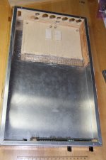
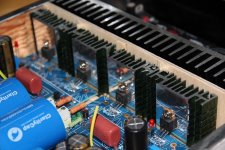
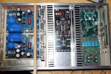
Please see my build pictures (as Salas asked) taken about 6-7 month ago when I just finished my FSP. I already uploaded them once, but for the guys who did not see....
Great looking cases
What are the VU meters for ?
To show you guys the principle
Stajo, does your boards hang on the powerfets legs at that end? Any other support?
Regards
I am trying to use your figures to predict the maximum output from the RIAA pre.
3mV is the specification for a 5cm/s groove modulation.
The typical maximum modulation is ~25cm/s
This would result in a maximum cart signal of 25/5*3 ~ = 15mVac
Applying 43dB of RIAA gain gives a maximum output of inv log(43/20) * 15 = 141.25*15 = ~2.12Vac
Are my numbers correct?
Is my method correct?
Hi Andrew
Take care my friend.
PS: Thank you for the math
Both the boards and the sinks has their own wooden support both under and over them on that side. On the other side its screw distances as seen on pic.
Yes, the 369'ers side was clear. So it lays on wood and is supported by wood on top. So no stress on the powerfets?
Regards
- Home
- Source & Line
- Analogue Source
- Simplistic NJFET RIAA