or you disconnect one amplifier and test the other one.
How is that relevant with dual transformers? The only thing the 2 channels share is the power cord (and presumably mains fuse and power switch).
What it gives with 470R dummies?
Approx 50,5 VDC
Btw Im in your hoods now. Just killed a z-foil. By heat while removal.
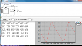
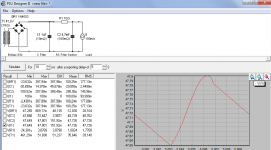
OK, beside the easy Z-kill which is grr@#%, while having 470R hooked as dummies try some RD value for 47-48VDC raw. It will do good to EMI and will keep calm VDC during a high mains plateau if ever. Bring up the Duncan PSU software and use 100mA as end load to gauge the about RD value. Resides between bridge and filter cap. But use crocks to confirm before installing. 2W-3W-5W should fit and suffice.
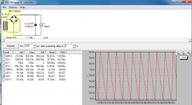
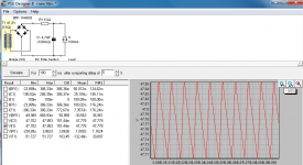
I was not worried about the ripple, rather confused about that the drop over the RD was 1,3 VDC when it dropped some 3 volts in total. But Im with you now, the C doesnt get the same camelbacks as without the RD. PSUD says 3,86 V pk-pk ripple over RD. 1,76 RMS.
Edit: You said dummies, I thought RD. My fault.
Edit: You said dummies, I thought RD. My fault.
Last edited:
I was not worried about the ripple, rather confused about that the drop over the RD was 1,3 VDC when it dropped some 3 volts in total. But Im with you now, the C doesnt get the same camelbacks as without the RD. PSUD says 3,86 V pk-pk ripple over RD. 1,76 RMS.
Edit: You said dummies, I thought RD. My fault.
1.364 RMS. Given the ambiguity on real internal resistance of your Tx, I think that you did pretty well on theory vs practice results.
1.364 RMS. Given the ambiguity on real internal resistance of your Tx, I think that you did pretty well on theory vs practice results.
Yes PSUD is remarcable if just inserting the right values. Trafo resistance is often the hardest imo, and affects big time.
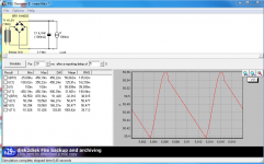
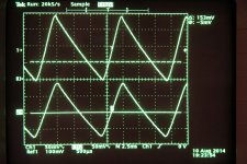
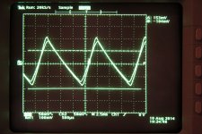
PSUD shows only slightly broader tops of the camelbacks with RD. Maybe more visible on scope. Kiddo goodnight time now tho. Later maybe.
When able probe across the dummies on AC coupling and look on the scope with a crock bypassing RD and without.
")
Smaller values looked peculiar but at 1 uF it starts looking round and nice. Did you have time to look at http://www.diyaudio.com/forums/analogue-source/129126-simplistic-njfet-riaa-1316.html#post4019478?
Attachments
- Home
- Source & Line
- Analogue Source
- Simplistic NJFET RIAA