Other then that maybe mark in some way which holes that can be used on either side on the big caps (C3). Brighter people then me (Ale M for ex) obviously tried bridging it in another way then thought on SSHV for example.
Edit: If the card is going to be marked as shown with the green lines, that is what I asked for ofc.
Edit: If the card is going to be marked as shown with the green lines, that is what I asked for ofc.
Last edited:
There is no + that's Eagle's "GPS". Square pads are cathode.
 Wasn't it always square for anode?
Other then that maybe mark in some way which holes that can be used on either side on the big caps (C3). Brighter people then me (Ale M for ex) obviously tried bridging it in another way then thought on SSHV for example.
Edit: If the card is going to be marked as shown with the green lines, that is what I asked for ofc.
The big + inside the lytic circles near pad are printable marks.
As I understand it differs from the manufactor, hence the confusion? On the caps wiki page it says:
"On a printed circuit board it is customary to indicate the correct orientation by using a square through-hole pad for the positive lead and a round pad for the negative."
When we come to leds:
„Round +
Square -"
At Express PCB tips it says:
„Position polarized parts (i.e. diodes, and electrolytic caps) with the positive leads all having the same orientation. Also use a square pad to mark the positive leads of these components.“
The big + inside the lytic circles near pad are printable marks.
C3 is preferably not a lyt as I understand it. I didnt mean polarity, just the holes. It might not show on the cards which are connected and which are not. Follow?
Enough with the pcb!
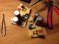
Here is my attempt at p2ping this thing.
It has space for a better c3 (obbligato), and needs a 2r2 resistor and a 200r potmeter until I can realise its not working. Its soon powered by a badly oscillating BiB. I´m hoping to pick up a Kenwood 4025 on thursday, so I´ll at least know about the problem.
Hoping for some honest input here. I know my way around the basics of electronics, but I´m in over my head here. As you can see, its mildly inspired by salas' layout. I could not see where R3 was, so I just put it underneath.
I know the upper board has some extra space on the line between c2 and c3, and the leds in salas' build had some space between them. The c2 c3 thing is annoying me. But, on the other hand, the beer was great!
Oh, and I really dont know how I´m going to mount this in a chassis. There is no extra space for mounts, since I went for the smallest size i felt safe with. Its hopefully going to fit inside my lp12. Hovering.
Here is my attempt at p2ping this thing.
It has space for a better c3 (obbligato), and needs a 2r2 resistor and a 200r potmeter until I can realise its not working. Its soon powered by a badly oscillating BiB. I´m hoping to pick up a Kenwood 4025 on thursday, so I´ll at least know about the problem.
Hoping for some honest input here. I know my way around the basics of electronics, but I´m in over my head here. As you can see, its mildly inspired by salas' layout.
I could not see where R3 was, so I just put it underneath.I know the upper board has some extra space on the line between c2 and c3, and the leds in salas' build had some space between them. The c2 c3 thing is annoying me. But, on the other hand, the beer was great!
Oh, and I really dont know how I´m going to mount this in a chassis. There is no extra space for mounts, since I went for the smallest size i felt safe with. Its hopefully going to fit inside my lp12. Hovering.
Attachments

As I understand it differs from the manufactor, hence the confusion? On the caps wiki page it says:
"On a printed circuit board it is customary to indicate the correct orientation by using a square through-hole pad for the positive lead and a round pad for the negative."
When we come to leds:
„Round +
Square -"
At Express PCB tips it says:
„Position polarized parts (i.e. diodes, and electrolytic caps) with the positive leads all having the same orientation. Also use a square pad to mark the positive leads of these components.“
C3 is preferably not a lyt as I understand it. I didnt mean polarity, just the holes. It might not show on the cards which are connected and which are not. Follow?
Any special point of assembly worth attention will be mentioned in a full guide. Lets see if a proto will work and measure well first.
Its been tested with a Bib 3 times. No problems. You can use double adhesive tape on some foam pad for mounting even.
Thats actually quite clever!
Some stupid questions:
How do I earth this thing for the lowest noise? Some special tricks? I plan to make a thin shielding for it, as I mentioned I hope to have it inside my turntable.
How long can I have the cables from the BiB with sensing? Would 1/2 meter be waaay to much or not so much of a difference?
Thanks again!
Best earthing is packaging and system dependent in each build. In general just a cable to chassis from the phono power node gnd with a floating reg suffices. Canned in shield box is very welcome for quietness. The Can should be its "chassis" in this approach. And then refer to some TT arm/chassis point probably. Convert the 1.1 in 2 wire with local jumpers on its output connector closing circuit locally if there will be EMI or instability with the long sense pair.
- Home
- Source & Line
- Analogue Source
- Simplistic NJFET RIAA