salas said:I have Supreme Silver/Oil in mine at the output.
Your both channels work OK now? Finished?
Here is your specific shunt reg, attached.
I'm having trouble with the other channel, which I'm looking at now and shouldn't have running tonight.
Thanks again for the reg sch.
I have tried Mundorf MKP & Supreme and find them excellent for the price. I have a couple of Silver/Oil on the way and I'm pretty sure of where they'll be going.
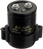
My question was meant about those huge smoothing caps that were pictured a few posts ago. The specs are incredible, and I'm wondering if they really would make an audible difference to my power amp, which is a very much modded Quad 405. I currently use Mundorf Mlytics there. Sorry for going off-topic.
Regards. Lee.
Thomo said:along with adding Salas' Shunt Reg design to my board layout.
Lee.
RCruz is going to throw a party! Has been waiting patiently for PCBs...
P.S. What exactly is troubling you with the second channel? Isn't it enough to copy the first one exactly? Don't you work on some test PCB already? Or is it P to P?
I rushed both channels p2p and messed one up. Well, messed both up actually, lol.
I'm now running stereo, but it's fairly late and we have neighbours both sides so I can't play at a decent volume. I will be testing more tomorrow, but 1st impressions are very, very good.
Thanks again Salas. This is so much better than the opamp stage I used months before. I can't wait to finalise it!
Lee.
salas said:
RCruz is going to throw a party! Has been waiting patiently for PCBs...
LMAO
A little O/T but, has anyone compared the vinyl of Pink Floyd's animals with the remastered cd? This vinyl on my office system is sooo much better than cd on my main system.
Lee.
This is going to be another major improvement in my system.salas said:
RCruz is going to throw a party! Has been waiting patiently for PCBs...
While I waited, I build a Maggedon psu for my TT. (500VA Toroid)
Big improvements in almost every aspect... better detail, lower noise floor, better attack and decay..... just like adding a dedicated psu on my CD53 Decoder

Hopefully Lee will soon provide us with the dividends of his awesome work.
Ricardo
RCruz said:
Hopefully Lee will soon provide us with the dividends of his awesome work.
Ricardo
The awesome work credit must go to the designer of the cct.
Lee.
salas said:I have also used M-Lytic 500V on tubes. Good, a little trebly I think, but clean. Nippon Chemi-Con KMH 105 C are 90% that good at much lower prices.
nice
Salas I thinks that I have found the mundorf source, price 25% lower
look the same!
An externally hosted image should be here but it was not working when we last tested it.
Attachments
RCruz said:
This is going to be another major improvement in my system.
While I waited, I build a Maggedon psu for my TT. (500VA Toroid)
Ricardo
You are flexing for the finals I see!
All sorted out and ready.Hi LeeThomo said:
LMAO
A little O/T but, has anyone compared the vinyl of Pink Floyd's animals with the remastered cd? This vinyl on my office system is sooo much better than cd on my main system.
Probably you are listening to a analog mastered copy of Animals... (I do not know any reissues of this particular take).
From late 80´s onwards, vinyl started to be made after digital recording master tapes... and now, companies trade "masters" in DAT format, so you have the CD common 20kHz "brickwall" and loose all the magic.
If you listen to "pure" analogic recordings, you can benefit from the very extended bandwith of vinyl that can go up to 75000Hz in some cases.
All this bandwith, mixed with the total absence of quantization makes possible the wonderfull coherent sound from vinyl... that is wy it sounds so much more real.
Note: Even after all the modds I did in the CDP, It can not compete with a good "pure analog" vinyl on my 30 year old RD80 in terms of pace and imagery.
Welcome to the world of high def sources.
PS:
Maybe SACD can outrun a TT ......

Ricardo
RCruz said:
PS:
Maybe SACD can outrun a TT ......
Ricardo
For what I reads NO
I hope No, I have burn to much money for analog

nicoch46 said:
For what I reads NO
Well, I never heard any SACD better than my über 53.... maybe you are right.... last Summer I heard a heavy TNT with big amps running B&W Nautilus and I could not believe the dynamics and clarity of the sound......
Next pass on the shunt regulator is here. The two transistor current source at the far left is to supply bias current to the zener outside the gain path of the regulator in order to push it up into the steeper portion of its operating curve - less output voltage change with input voltage, higher gain, somewhat less noise. The capacitor across the zener (with added resistor to simulate ESR) provides extra quieting. The JFET current source to the right is used to present a stable drive current to the upper bipolar-MOSFET current source. The PNP transistor in that current source works against the bias current source, determining the ultimate operating point of the transistor in the MOSFET-bipolar current source. Using a higher value of bias current would dictate a somewhat higher base voltage for a given current source set point.
Both current sources could be replaced with resistors, with some compromise in performance. The left-hand source is set at ~2.5ma, and the right hand at ~1ma. The left-hand souce is bipolar to allow greater freedom in setting the unregulated input voltage, as it sees the full unregulated voltage until the cap across the zener diode charges up, but must also operate properly with the zener stealing a good hunk of the voltage headroom. The right hand current souce has no such problem, as it sees a fixed voltage. The right hand current source could also be implemented as a bipolar "ring of two", with the penalty of greater complexity. The resistor in the JFET current source drain drops the voltage seen by the JFET to a safe value, allowing use of a cheapo JFET like the 2N5459. A 5457 or 5458 could also be used with a change in the source resistor. This resistor will need to be picked by experiment for the proper drain current anyway, as the its actual characteristics will vary from those of the simulation.
The bipolar transistors used (MPSA56) 600 ma, 80V, could be replaced with anything with similar ratings.
I changed the main MOSFETS to IRF510 and IRF9510 to prove a point - the smaller FETs work well. Larger FETs will work, too, but will slow down the regulator a bit.
Using a high quality, low ESR cap at the regulator output is key to good performance, as it provides the current for fast transients until the regulator responds to take up the slack. This capacitor also stabilizes the regulator - it likes that big cap on its output. Panasonic FC or UCC LXZ series capacitors work well. Trying to do something similar using only film caps with negligible ESR might compromise stability. I tried adding a modest amopunt of film bypass to the smulation withoput noticably affecting the response. It might be good to add some to counteract the main capacitor ESL.
Attachments
Here's the simulated response - still fast, with no funny stuff. The overshoot and undershoot represent the time period during whch output capacitor buffers the load transient. The initial edge is the load transient working against the output capacitor ESR. The offset voltage after the transients settle out represents the effective output impedance of the regulator. this is about 2 mV/0.1A = 0.02 ohms - not bad for a simple circuit. This is just a simulation, so the results should only be used as a rough figure of merit, but a real circuit should perform in similar fashion.
Attachments
Great concepts here wrenchone. I like the Wilson current sourcing and the chunky output cap. I sadly miss the discontinued Panasonic HFZ series here. Very fast and really long life. I don't know if there is still NOS around. I would prefer a P-Mosfet at the shunt position, with npn's at its drive. This reg obviously demands a PCB. Technically is well taken care of and will perform closer to ideal. Current sourcing and fine trimming in abundance, still not really deviating from my initial block. 5459 is one of my favorites, and I know that you hate exotic parts. If someone's making the Salas RIAA though, will end up with enough non matching quieter 2SK170 spares to use around. Of course this ''not that simplistic'' but ''I am not scaring anybody'' regulator, must be made and get auditioned by some curious soul. I kept mine under the ''simplistic'' concept on purpose, so it would stay accessible to many more and in sync with this thread's spirit. Heavier Mosfets I used on purpose too, so it won't oscillate easily into nobody's inexperienced hands, especially when playing with favorite capacitors. And sometimes, fast, but not super fast, is lending itself better to DIYers. I can only imagine what it may happen for music if it achieves even +10% additional subjective performance over mine, since the ''simplistic'' already had given roughly +25% to the RIAA VS LM317's.
I am very grateful for your time and intellect, adding value to this thread. Cheers.
P.S. Now all that remains is some people putting everything RIAA and Shunt on PCB, and posting Gerber files here, so they can royally copy us in the Far East kit stores! Naah! I am joking! We do it all for vinyl! Please copy us!!!! Bring people closer to music once again!
I am very grateful for your time and intellect, adding value to this thread. Cheers.
P.S. Now all that remains is some people putting everything RIAA and Shunt on PCB, and posting Gerber files here, so they can royally copy us in the Far East kit stores!
Naah! I am joking! We do it all for vinyl! Please copy us!!!! Bring people closer to music once again!Getting very addicted to vinyl!
I'm trying to source some of those Siver Mica caps, but the available values are limited. I've used brand new Silver Mica from Farnell many times and really like them, but they are expensive for the values I need here.
How many caps is it ok to combine to get the required uF? I read somewhere that you shouldn't use more than two in parallel.
Regards, Lee.
Hi Lee, 2 are OK. You can use a PP base for 80% of your needed capacitance and bypass with a Silver Mica. You can make it more compact and cheaper that way, putting the Mica sound well in to play. Off course a ''single malt'' Silver Mica component value would be optimum. Check E-bay for those Russian beauties.
Is your TT and cart in good health and alignment? Checked VTF, VTA, overhang, leveling, geometry, speeds etc? What are your listening impressions of the RIAA by now? Photos would be nice.
Is your TT and cart in good health and alignment? Checked VTF, VTA, overhang, leveling, geometry, speeds etc? What are your listening impressions of the RIAA by now? Photos would be nice.
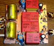
Here's a photo of my first attempt at putting a 'Salas Pacific' RIAA together. I've mostly just used R's and C's that were available at my local electronics store (Maplin), apart from the Audio Note output caps which I had already.
First impressions are favourable. The sound has more body and presence than before. 'Before' was with opamps: The Hagerman Bugle with LM4562s.
Thanks to Salas and all who have contributed to this interesting thread.
First impressions are favourable. The sound has more body and presence than before. 'Before' was with opamps: The Hagerman Bugle with LM4562s.
Thanks to Salas and all who have contributed to this interesting thread.
Attachments
HI jonners ,do better
hificollective
the wima ar not so good ,claritycaps good an cheap and they have polystyrene-mica(this sound more brigth)
same resistor ..a rload make big difference ,-kiwame-holco-dale(play with value)
try connect the out rca gnd at input rca gnd
better dual mono design
hificollective
the wima ar not so good ,claritycaps good an cheap and they have polystyrene-mica(this sound more brigth)
same resistor ..a rload make big difference ,-kiwame-holco-dale(play with value)
try connect the out rca gnd at input rca gnd
better dual mono design
- Home
- Source & Line
- Analogue Source
- Simplistic NJFET RIAA