QH had reported problems with D1 in that layout I remember. Not sure on what conditions.
I'm waiting for the transistors, will strip away the big zener as you suggested salas
")
I'm waiting for the transistors, will strip away the big zener as you suggested salas
The zenner for IRf , I not like use it,
but On the PCb you can use, there are 2 hole for use under board!
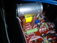
You are fortunate to have a friend with Caddock's, if your friend have 1 or 2 for me I will appreciate very much.
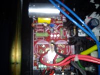
I´ve got the Caddock in place. I hope i had a bit time this weekend to listen to it...
An externally hosted image should be here but it was not working when we last tested it.
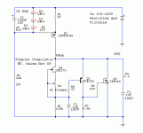
I'm going to build very soon (as soon as I'll get the parts) ShuntReg for a CDP I have (a very good sounding one, with tubes analogue stage). Both channels together draw about 20mA and the present HV supply is 190V (originally a Zener and BJT series regulator).
My suggested schematic is attached.
All comments are welcomed.
The bridge rectifier B1 and the electrolytic capacitors C103 and C104 are already in the circuit (Nichicon). R102 will be modified to have the Shunt's CCS drop 50V.
I thought of paralleling the electrolytic capacitors C103 and C104 with 0.1u film capacitors, for better RF filtering. Is it a good idea?
Few questions:
1. I don't know how to calculate R3, R4 and R6?
2. Is a stopper resistor at the base of T1 necessary, or a good idea?
3. In the CDP there are 2 PCB's, one for each channel. (The ShuntReg will supply both channels). At the HV input of each channel there is a 220u/400V electrolytic capacitor (Nichicon). Should I remove them? Or testing with a scope that there are no oscillations is good enough?
Attachments
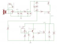
You can live with less drop than 50V in this version and keep CRC ripple filtering higher. Aim for 25V drop. Go for less R only if you will feel its better subjectively later on by experiment. Don't use 0.1uF films across your main filtering caps. They usually create resonances. For R3 you look for 5-10mA through the LEDs. 43K is fine for 220-250V DCin in your case. R4 100-120K is fine for running the K170 at 1-2mA. R6 5K6 for keeping the loop gain as high as in the standard SSHV design and the MJE350 cooler. A stopper for it is a good idea and its included in the standard design, has to do with the phase also. 47R. Use a 47R in line with C1 too. If there are no oscillations with the local Nichicon 220u, listen with and without, they may decouple the wiring better or just slowing down the reg. Good luck.
Thanks Salas, your assistance is highly valued.
An updated schematic is attached. Please see if you may have any comments about it.
A question, out of curiosity: all over the thread you said that 50V drop on the CCS is the ballpark and here you recommend to start with 25V - why is it? What makes this circuit different? Is it that the use of JFET instead of ring-of-two as a voltage source is more effective?
Attachments
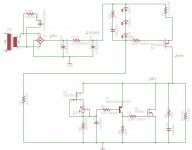
Your schematic from Eagle looks OK I think. For the SSHV in guide post #967 I wrote ''15V DC IN-DC OUT is the lower limit for adequate performance''. 50V was firmer in first iteration, this iteration is sounding OK to me at 25V with less pronounced gain at 50V. You may judge for yourself in your system, but you can be technically OK from 15V up.
I would get it down to 200Vin by dropping on the R element. That drop has to do with how much current is absorbed by the reg. Its constant, Ohm's law will predict, same for the power dissipation (RfilterVdrop*Iccs). Use 3 times that dissipation figure for R wattage spec.
Attachments
Salas, great ... thanks alot !
Normally at valve pre there is at least one RC filter for each chanel
to separate the channels. Will you see a necessity to have one reg
each channel or is it okay (enough channel separation) to go from
the reg´s output directly to anoderesistor left and right ?
Greetings Ulf
Normally at valve pre there is at least one RC filter for each chanel
to separate the channels. Will you see a necessity to have one reg
each channel or is it okay (enough channel separation) to go from
the reg´s output directly to anoderesistor left and right ?
Greetings Ulf
Q2 collector voltage
What should the voltage be at the collector of Q2?
My circuit was working...and stopped. I'm using 310V in, targeting 250V out, using 33 ohms for R1. I need about 10mA current for the circuit. I'm using a 35K load to test with. My circuit is identical to Salas' (except for R1) original post #3 in this thread.
Any ideas on what might be happening?
Thanks!
Gary
You mean the BJT ring Vref one with Q2 2N6520? You have lost Q2 most probably. The collector voltage to ground should be at output Mosfet's VGS. I.e. 2-4V. Make the collector resistor R4 4.7k for less heat on Q2 after you exchange it if it is dead indeed, and use R1 for not over 30-40mA in your case. So you cool down the whole also. See what it runs with now 33R (IR1=VR1/R1) and find a value for 35mA.
You mean the BJT ring Vref one with Q2 2N6520? You have lost Q2 most probably. The collector voltage to ground should be at output Mosfet's VGS. I.e. 2-4V. Make the collector resistor R4 4.7k for less heat on Q2 after you exchange it if it is dead indeed, and use R1 for not over 30-40mA in your case. So you cool down the whole also. See what it runs with now 33R (IR1=VR1/R1) and find a value for 35mA.
Salas,
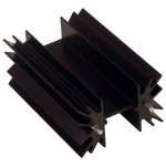
As always, your time is generous and much appreciated. Instead of popping another Q2, I ran the LT simulation and it was showing about 4V. I will try again with the 33 ohm and switch R4 to 4.7K and see how that looks. The simulation also showed the 2N6520 at a dissipation of 800mW. A bit high for such a little guy - the max should be 600mW. Also, Q3 (IRF840) was running very hot, 125C on the heatsink. The heatsink used is attached (2.6C/W) DK part HS380-ND. That heat seemed way...too much for reasons unknown.
A second question - has the design on post #967 superseded the original design on post #3? perhaps I'm a little behind.
Cheers, thank you
Gary
Attachments
Heat indeed. 4k7 should help. Do you have any TO-92 mini sink to put on Q2 also? How much dissipation it shows on your sim for 4k7? If you now run 50mA excess X 250Vo = 12.5W steady...If you set 35mACCS-10mA to load=25mA excess it will be 6.25W, big relief for the IRF840 on that smallish sink. Yes the newer one with the simpler Jfet Norton Vref I find better in general. But listen to the one you got first so to do your own comparisons later with the newer.
- Home
- Amplifiers
- Power Supplies
- Simplistic MosFET HV Shunt Regs