Don't know if another part will work better in practice, I have only used 1N5383B once directly point to point. There was trouble on some issued boards from a 3rd party with some layout distance. Interestingly the 200V enhancement mode Mosfets work without clamps with up to 300V+ Vo regs in many reported builds.
Don't know if another part will work better in practice, I have only used 1N5383B once directly point to point. There was trouble on some issued boards from a 3rd party with some layout distance. Interestingly the 200V enhancement mode Mosfets work without clamps with up to 300V+ Vo regs in many reported builds.
I have read on various posts where you have indicated that layout is critical, I plan to follow the advice and insure all of the key points are applied in my layout. I will be using your design in my Class A power amplifier, for both the screen regulation (350V) and input driver supply (400V) regulation. I do not plan to regulate the plate supply of the output tubes (6L6GC)
I am looking forward to hearing the difference between the Maida regulator and the Salas shunt!
You are edging its VoMax zone. Protection, layout, and sinking will be critical. Use MJE5731A 400V for the BJT driver Transistor. Gear up with some alternative clamping Zeners and spare PMOS also.
Salas, at the driver current required, the Pd is about 10W on the IRFP9240
Do you mean to use the MJE5731A instead of the IRFP9240 for the 400V driver supply?
Where is the maximum output voltage (VoMax) specified for the IRFP9240? I do not see this on the data sheet.
Thanks,
Gary
MJE5731A Instead of MJE350. BVdss is the max breakdown in IRFP datasheets.
Here's the line from the Vishay data sheet:
Drain-Source Breakdown Voltage VDS VGS = 0 V, ID = - 250 μA - 200V
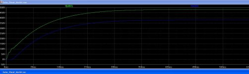
So I do not understand: With the 100V clamping zener, the simulation shows the differential voltage (Vds) at just...100V. So why is this a problem?
With this in place, the device never sees more than 100 volts difference from drain to source. See attached screenshot - green trace is input, blue trace is output.
Please explain, as it is not clear - I thought that's what the purpose of the zener was.
Attachments
Its no problem, that is the idea, to keep the Vds in bounds during start up. Maybe the Zener junction capacitance gave problems in conjunction with layout inductance on a board attempt. That situation I did not experience personally with p2p. The BJT driver (error amp) of the shunt IRF840 current element has to meet your 400V spec also.
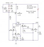
I am using the SSHV for a tube-preamp. Schematic as attached. The reg is in the my "signal" chassis while the powersupply is external. The wire between the two chassis is about 1m long. Would it be beneficial to decouple the supply with a capasitor to ground right at the inpt of the SSHV printboard?
Attachments
After SMHVSR for B+ is better go directly to anode tube or put between the reg & the anode tube one resistor + one cap?
Doing so you will defeat the benefit of the shunt regulator, Zo after the resistor will be high, while Zo of the shunt regulator is very low.
I am using the SSHV for a tube-preamp. Schematic as attached. The reg is in the my "signal" chassis while the powersupply is external. The wire between the two chassis is about 1m long. Would it be beneficial to decouple the supply with a capasitor to ground right at the inpt of the SSHV printboard?
Yes, it can be highly beneficial, it is recommended. A film capacitor between 0.1u to 1u should do it. In any case, it will do no harm.
Doing so you will defeat the benefit of the shunt regulator, Zo after the resistor will be high, while Zo of the shunt regulator is very low.
If I put a choke between the shunt regulator & the anode tube, will be the same?
If I put a choke between the shunt regulator & the anode tube, will be the same?
Anything (other than plain wire) you will put after the shunt regulator will result in higher Zo. For one, there is no need to put anything after the shunt regulator. Second, anything you may put after the shunt regulator can only degrade it's action and benefits.
There is a point, though, to take care of a very good filtering before the shunt regulator. CLC, or LC are good options, though CRC or CRCRC are good as well. Probably CLC or LC or CLCRC or LCRC are best.
finished the positive part of my dual 300V supply for Exstata. Its P2p.
The heatsinks are a bit small (the ones for exstata's PSU), so the tempereture on the heatsinks stabilized after 15 minutes.
For irf9610 to 50 C, and for irf840 to 80C
(A bit high i guess. Adding bigger heatsinks is a problem in my chassis design, so i will add a fan. For test i just put up a 12'' PC-fan, and the tempereture fell to only 40 C")
Finished the negative part (after some "discussions" with (now dead) mosfets ...)
The initial test says that the total I though R1 (47R) is only 40,5mA and the Iout through test-R is 36mA ... is that stabile?
If your load consumes 36mA, up your CCS to 56-60mA.
do you have a post, or formular - about what value to change R1 into? (I suppose R1 is the target)
do you have a post, or formular - about what value to change R1 into? (I suppose R1 is the target)
Post #4: http://www.diyaudio.com/forums/power-supplies/134801-simplistic-mosfet-hv-shunt-regs.html
- Home
- Amplifiers
- Power Supplies
- Simplistic MosFET HV Shunt Regs