Hi salas,
Thank you for your concern")
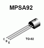
I bought a bug of MPSA92 and I'm nearly ready to begin soldering my first prototype (I'll post photos when its done) based faithfully on the schematic you made for me.
The info about MJE350 is very useful though. Some 170's that I have are GR grade. Is there any more available Fet that it could be used isntead of 170 ? (It's me again )
)
Thank you for your concern
I bought a bug of MPSA92 and I'm nearly ready to begin soldering my first prototype (I'll post photos when its done) based faithfully on the schematic you made for me.
The info about MJE350 is very useful though. Some 170's that I have are GR grade. Is there any more available Fet that it could be used isntead of 170 ? (It's me again
)You can use the GR. Its only one needed and you may happen to have one that does not match well with the others for a an audio schematic. If you can get any other NJFET with VGS(OFF) about 1V or lower, then its OK. Its either we use a TO92 HV PNP BJT (Q2) with the resistor and about 1.5-2mA so its dissipation is OK but it has enough Hfe at low current, or we CCS boost a power PNP HV part which has enough Hfe only in high mA but can take heat with sink. The low pinch off is needed so the NJFET IDSS CCS can work in the low voltage margin of the VGS allowed by the shunt NMOSFET. It has to see double pinch off margin so to meet the Jung criteria for performance. Because the loop gain of the regulation comparison that the driver does is gm(Q2)*Rload(R4), a CCS instead of an R will show very high impedance and up the gain. So its a nice partner when the gm is low, but the BJT part can be sinked and work at some mA. Of course if something oscillates, better keep spares!
Anyway, this is experimental region due to necessity or curiosity. The sound will change too. A 47R series resistor to the PNP BJT base would help avoid sudden death. It also can be used with the MPSA92 if it shows failures during service life with some reactive load or not so good, long cabling to load etc.
Anyway, this is experimental region due to necessity or curiosity. The sound will change too. A 47R series resistor to the PNP BJT base would help avoid sudden death.
It also can be used with the MPSA92 if it shows failures during service life with some reactive load or not so good, long cabling to load etc.revintage said:Hi Salas,
Ripple seems a little high when I sim this. Maybe I have the wrong ripple for the rawsupply. How much ripple do you consider at input?
Hi salas!
I have decided to next build a version of the hv shunt to use with my current tube head phone amp.revintage, I have simulated the hv shunt, as I always do a bit of simulation before getting real with a circuit, and I got less than 1mV ripple at the output, with 1V AC p-p input, biased at 300V DC. Is this similar to what you get?
Use a heat sinked power HV PNP BJT driver for the 840 and make its Rload a JFET IDSS CCS if you wanna drop the ripple. But don't strive more for theoretical perfection by manipulating the main CCS etc, bcs this shunt has been voiced for tone. It plays fluidly with a CLC pre filter as it is.
ikoflexer said:I got an mje350 on hand that I'll probably use instead of the mpsa92, if that's what you mean. I also don't have any 840s, but I got some irfpc60 which I think should work.
Don't forget to mini sink it, because its gonna dissipate enough when you gonna CCS it with a BL from collector to ground. Good luck. If you see it oscillating, and can't solve, don't worry, revert to the standard one, Its good enough.
Marinos said:Hi salas,
Just to be sure...
MPSA92 C & E pins are reversed compared to BC560's. Aren't they ?
Attachments
It's a trafo of unknown origin, have no idea the power specs on it. The amp is a variation of post #5 on this page
http://www.audiokarma.org/forums/showthread.php?t=163886
I definitely need a solid trafo to power the shunt+power amp. It was just my oversight.
http://www.audiokarma.org/forums/showthread.php?t=163886
I definitely need a solid trafo to power the shunt+power amp. It was just my oversight.
P.S. If you measure the voltage drop across R1 it will give you the CCS current by solving Ohm's law for I. Vin-Vg=LEDsVdropTotal. ICCS=((Vin-Vg)-VGS)/R1. See to set R1 for a current just double the idle consumption of your load (2 channels). Maybe you use it too hot right now for no real reason. There is a chance that your now trafo can hold if you set the constant current in the CCS conservatively. In general many transformers prove wimpier than we might have thought when constant current is needed and/or buzz.
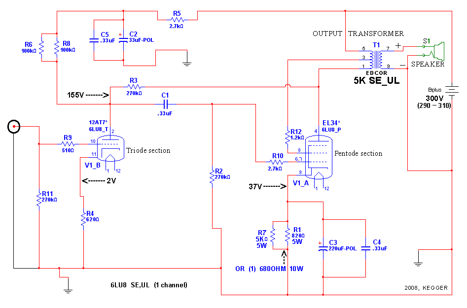
Here's the schematic.
I haven't measured the current draw in a while, but I think it's around 120mA total, for the amp.
As for the jfet under the driver bjt, are you referring to R4 in this schematic?

Yes, I have replaced R4 with a jfet, but since the thing didn't work properly, I reverted to a resistor until I see it walk, then we can make it fly with a jfet
I haven't measured the current draw in a while, but I think it's around 120mA total, for the amp.
As for the jfet under the driver bjt, are you referring to R4 in this schematic?
Yes, I have replaced R4 with a jfet, but since the thing didn't work properly, I reverted to a resistor until I see it walk, then we can make it fly with a jfet
Aha, so this is a proper low power SE amp that you use for headphones. Grado? With 120mA class A load, I would set the shunt at 200mA with 350V input after CRC or CLC prefilter, 300V out. We are talking 60W constant consumption for the tarfo, 10W dissipation on the IRFP and 24W on the 840 with load attached. 200VA trafo at least. I know, the sound will be awesome with a power amp fully shunt regulated. But economically and environmentally...Kyoto protocol issued to Iko.
ikoflexer said:As for the jfet under the driver bjt, are you referring to R4 in this schematic?
Yes, its R4 in all schematics. The schematics are the same basically, the R values or proper voltage PNP BJT type change due to different voltage or consumption scaling for individual needs.
I'm very happy with my sony mdr-v6 headphones. A friend has a pair of good Grados and we compared; I saw no reason to move. Yes, other people use this amp with the edcor OTs and speakers. I modified the amp slightly to accommodate a couple of 250V-6V power trafos (tested for frequency response) which proved a great match for the sony headphones (impedance around 60R). The amp is not on the sweet and syrupy side, rather sounds detailed, fast, and furious
Electricity is cheap here... hey, if I was really into efficiency, I'd only use class-D amps ahm... I don't think so. Especially after my 41hz truepath project gave me grief like nothing else (with all due respect, the board is designed for little ants).
Electricity is cheap here... hey, if I was really into efficiency, I'd only use class-D amps
ahm... I don't think so. Especially after my 41hz truepath project gave me grief like nothing else (with all due respect, the board is designed for little ants).You can use a Maida, but I am not sure its gonna pass 120mA reliably. The only difference will be the CCS that it does not have. Another thought is, since you use it for headphones, and it is Class A, maybe it does not swing much so you can try to set the shunt say at 140mA, that will be a strong relief to the now trafo. Listen to know if it compresses at all. If not its OK. I would try that first before making a Maida. Which sounds far lesser in tone quality anyway. How many mA did you use initially and the trafo did not hold?
- Home
- Amplifiers
- Power Supplies
- Simplistic MosFET HV Shunt Regs