salas said:Milen:
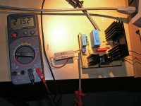
They look OK for the moderate cuurent and voltage difference you gonna use. Put thermal grease for the surfaces to contact well. The aluminum looks rough.
hi Salas
yep the aluminium is rough. i cut them into half myself. lol. they are cheap. they small one on the back of the irfp9240 is just around 15cents.
thermal grease? does the drain of the mosfet need to be isolated from the heatsink?
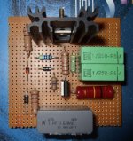
i think its there on the top left conner. just not labelled. Gary?JC951t said:Hi Gary,
You missed out Q1
erwin
If the 2 Mosfet heatsinks are separate, and no one of them will ever touch ground, you can not isolate them, but if you touch them they will be on high voltage. Since there is always chance for an accident, I would highly recommend you use mica spacer pads and thermal grease, plus isolated screw for 840, 9240 normally has isolated screw eye. Best of luck with your project, let us know more when ready and listening.
Hi salas,
I would like to try your regulator in a a low voltage triode line stage. The target voltage is 90 Volts.
Could this be done with simple changes to the schematic at post #2 or use the schematic as is and drop the voltage to 90 volts using an RC ?
Your advice will be much appreciated
I would like to try your regulator in a a low voltage triode line stage. The target voltage is 90 Volts.
Could this be done with simple changes to the schematic at post #2 or use the schematic as is and drop the voltage to 90 volts using an RC ?
Your advice will be much appreciated
Marinos said:Hi salas,
I would like to try your regulator in a a low voltage triode line stage. The target voltage is 90 Volts.
Could this be done with simple changes to the schematic at post #2 or use the schematic as is and drop the voltage to 90 volts using an RC ?
Your advice will be much appreciated
What is the bias current?
Ok...
Half of shame on me ...(as we use to say in our country)
In order to use existing stock (you know, thousands of parts gathering dust) I have the following questions:
- Can I use MJE350 instead of MPSA92
- BC560C instead of B
- Taking the necessary heatsinkings precautions, what's the maximum input voltage that I can feed the shunt with ?
Marinos said:Ok...
Half of shame on me ...(as we use to say in our country)
In order to use existing stock (you know, thousands of parts gathering dust) I have the following questions:
- Can I use MJE350 instead of MPSA92
- BC560C instead of B
- Taking the necessary heatsinkings precautions, what's the maximum input voltage that I can feed the shunt with ?
200V DC in will give 10W dissipation to the CCS Mosfet in your case. I would not push it more, its not practical when needing 90V out. Adjust a CRC so to pre filter enough and lose some there.
The MJE350 will work, but I have done no simulations with that. It can compromise it a bit if its Hfe is not that strong because of the low current it biases it here.
BC560C even better.
revintage said:Hi Salas,
Ripple seems a little high when I sim this. Maybe I have the wrong ripple for the rawsupply. How much ripple do you consider at input?
Its not meant to be a great ripple filter. I made it with always assuming at least a CRC or lightly CLC pre filtered DC input. It says ''Rectified and filtered'' on the schematics. Its a part of the philosophy behind this reg so to make it simple and with the tone I wanted. That is why I don't boost the CCS with current sourced controller BJT, just LEDS. You can consider up to 100 or 200mV P2P input ripple just for test purposes, but in reality, after a typical CRC that is so common in HV tube practice, it receives much less.
Still waiting for the custom transformer to test my shunt reg....
BUT, while I was at it... I also built a Maida regulator with an IRFS450 / LM350 combo for my Aikido headphone amplifier.
After I flipped the switch it started to work flawlessly, only a few turns on the trimpot was needed to set the desired voltage.
Very much to my surprise it generates very little heat, after an hour the Mosfet heatsink just gets warm to the touch.
Which leads to a question (OK, doing a bit of threadjacking here, but it basically also applies to the HV shunt reg") ): How much voltage should be dropped across a Maida regulator? Right now I am dropping 35V...
): How much voltage should be dropped across a Maida regulator? Right now I am dropping 35V...
First listening impressions were very positive... the amplifier is much quieter than the proverbial churchmouse
I hope I can do some comparing once I have the shunt reg running.
PS Total cost of the Maida was a little over 10€ using parts from my parts bin, surplus and items I scored on E-prey...
BUT, while I was at it... I also built a Maida regulator with an IRFS450 / LM350 combo for my Aikido headphone amplifier.
After I flipped the switch it started to work flawlessly, only a few turns on the trimpot was needed to set the desired voltage.
Very much to my surprise it generates very little heat, after an hour the Mosfet heatsink just gets warm to the touch.
Which leads to a question (OK, doing a bit of threadjacking here, but it basically also applies to the HV shunt reg
): How much voltage should be dropped across a Maida regulator? Right now I am dropping 35V... First listening impressions were very positive... the amplifier is much quieter than the proverbial churchmouse
I hope I can do some comparing once I have the shunt reg running.
PS Total cost of the Maida was a little over 10€ using parts from my parts bin, surplus and items I scored on E-prey...
Attachments
The Maida I have used a lot. Its a high value for money series DIY reg. Basically an HV component ''shields'' LM317 from high voltage. The Mosfet versions sound better to me. There is normally a 12V Zener there. You need to drop double its voltage Vin-Vout so for the Maida to regulate well and most importantly not to see very low frequency pumping instability. Theoretically 15V would be enough, but I have never seen it working greatly under 25V. 35V you got is practically best, because it will keep it OK during mains voltage drops. Also it works OK up to 70-80 mA. Its large ratio setting resistor gets hot during work, and the Mosfet can easily die when probing around. A shunt is a hot curious beast that wastes power and presents better audio tone. Another story.
Edit: Here is a Maida example of mine, using IRF840 & LM317.
Edit: Here is a Maida example of mine, using IRF840 & LM317.
Attachments
Marinos said:Ok...
- Can I use MJE350 instead of MPSA92
In case you haven't got a -300V PNP TO92 yet, I thought of a way to use your MJE350 efficiently. If you sink the MJE350 for 2W dissipation you can use a 2SK170BL in the place of R4 (1k2). This NJFET has very low pinch off and it can work nicely in the VGS voltage bracket of the shunt Mosfet. Connected as an IDSS CCS (drain towards the MJE collector, G,S tied together to ground) it will run constant current through the MJE. That will up the performance quite a lot.
- Home
- Amplifiers
- Power Supplies
- Simplistic MosFET HV Shunt Regs