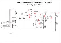
No, 100mA is roof if with depletion 10M45S hypothesis. This circuit we talk, goes as you know, by changing R1.
R1=20R, R2 & R6=470R looks good for that current you want. Why just don't modify one you already have, and start at lower safer current to see if the simpler Vref works OK first?
Thanks for sending gift.")
R1=20R, R2 & R6=470R looks good for that current you want. Why just don't modify one you already have, and start at lower safer current to see if the simpler Vref works OK first?
Thanks for sending gift.
No, 100mA is roof if with depletion 10M45S hypothesis. This circuit we talk, goes as you know, by changing R1.
R1=20R, R2 & R6=470R looks good for that current you want. Why just don't modify one you already have, and start at lower safer current to see if the simpler Vref works OK first?
Thanks for sending gift.
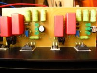
Ok! now I use this cricuit! And v-out, and I out
I use 80ma for my pre! it ist good sound, the are a litle hum, i think by my tranformer!
thank
Attachments
Last edited:
Hum is irrelevant to the reg. Its GND or Hum field. Do you run heaters heavy AC to heater regs lines on same board? Why 100R R6? Don't make board before you chek new one point to point OK? Its not tested yet.
Ok! i make 2 board I try do it for this cricuit, Do you see in My draw cricuit!
I see wrong R6. And don't run heavy heater currents and cables near the shunt boards or combining on them. Use individual heater reg boards away.
Ok! i think I draw lay out Salas shunt HI , AndCan you help me???
ok??
Until now here are my impressions.
This regulator beats any other regulator i have tried, tube, mosfet series, of course including brute force power supplies by quite a big margin. Inrcredible life like presentation, accurate imaging and impressive attack and dynamic appearence of instruments. And all this with just 20V Vin-Vout. The transformer i use cannot handle the current drawn by the shunts. The only drawback is that when i power the regulators i get Vout = Vin and after a couple of minutes it starts dropping voltage. I'm not sure how normal is this and how good it is for the tubes. I hope until the end of the week to have a couple of higher voltage transformers to implement dual mono. I will come back then.
Congratulations Salas for your design. These regulators are singing.
Also many thanks to disco for the PCB design.
Attachments
After speaking earlier for dual mono implementation, i would like to ask for recommendations about regulator ground wiring.
Having in mind that the preamp board has seperate B+ inputs for the 2 channels but common ground input i can think of 2 grounding scenarios.
1) Connect all grounds (rectifier ground, smoothing caps grounds from both channels , both regulator board grounds and preamp board) to a point very close to the preamp board ground input.
2) Connect each channel grounds (rectifier ground, smoothing caps from each channel and preamp board) to a point very close to each channel's regulator ground. To do this i should wire 2 seperate ground wires from the single preamp board ground input.
I will be very happy to see your suggestions on these or other grounding scheme for optimal performance.
I would think option 2. But we can never know optimal grounding for a system if not hands on. So dont count much on our opinion, just experiment with your options.
P.S. As you use only 20V Vin-Vout now, I don't think that this can put your tubes in any danger regarding your former question about starting high. Dont shoot for more than 50V dif with your new TXs. You could have enough local capacity on your pre that holds high. Use some bleeder resistors for your final CLC cap and preamp's local decouplers. Say just 1mA. So it all safely discharges after power off.
P.S. As you use only 20V Vin-Vout now, I don't think that this can put your tubes in any danger regarding your former question about starting high. Dont shoot for more than 50V dif with your new TXs. You could have enough local capacity on your pre that holds high. Use some bleeder resistors for your final CLC cap and preamp's local decouplers. Say just 1mA. So it all safely discharges after power off.
- Home
- Amplifiers
- Power Supplies
- Simplistic MosFET HV Shunt Regs