
Oliver, at what output voltage is your regulator? I experienced irregularities when I went over 280V / 80mA.
142V he uses
Nope... This is my second reg running at a lower load... The one I meant sits in my Aikido and puts out 215V into a 58mA load... Haven't measured voltages for quite some time as it is working absolutly trouble free.
http://www.diyaudio.com/forums/tubes-valves/134801-simplistic-mosfet-hv-shunt-regs-35.html#post1804305
Anyway... I'd call it medium voltage...

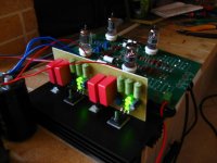
It sings!
More pictures and sound impressions will follow soon.
Hi manamanam!
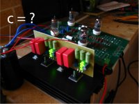
What the value of filter ? C-R-C? befor conect to Salas shunt?
An V-out?? And Ma??
thank!
Im my system C-L-C= 220uF- 470R-220uF to Salas shunt. but is not noise, and sound is good, there are a litte hum, when i use large volume?
But I dont know???
Attachments
Last edited:
Hi quanghao,
I have 47uF film cap --> 10H choke --> 2X100uF film caps in parallel.
Then i split to the regulators.
No noise, no hum, dead silent.
Good! You use film cap, the sound is ve ry exellent! I like MKP cap to supply!
Ok! it is good! You use 10H choke Is not noise and hum!
You filter by R? you can try do that, i think it is stil hum, im sure!
Thank!
I have tried also C-R-C. No hum at all. No hum even without regulators.
Just C-R-C or C-L-C.
I think that your hum problem comes from another source. Maybe interference from transformers.
Ok! thank! what lowest value capacitor you used? ,No noise, no hum! and R filter??
Because I want use all MKP cap for thi Shunt!
thank you very much!
Manamanam is absolutely right... even with a simple CRC there should be no hum whatsoever. So it might be grounding issues or other..?
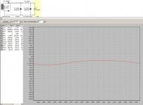
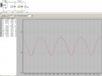
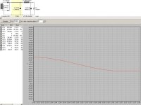
I did very quick and dirty simulations with PSUDII for different pre-reg configurations just to give you an idea how it affects ripple before the regulator. Salas mentioned something at the very beginnig of this thread of how much ripple before the reg is acceptible but I don't recall the number (300mV...??)
I must admit that I even have a tiny bit more than this in the Aikido (voltage doubler using 2x22uF MKP, 500R, 4x68uF --> regulator) but I'm having no hum at all.
OK, here goes (and don't hesitate to kick me when you spot any obvious mistakes):
I did very quick and dirty simulations with PSUDII for different pre-reg configurations just to give you an idea how it affects ripple before the regulator. Salas mentioned something at the very beginnig of this thread of how much ripple before the reg is acceptible but I don't recall the number (300mV...??)
I must admit that I even have a tiny bit more than this in the Aikido (voltage doubler using 2x22uF MKP, 500R, 4x68uF --> regulator) but I'm having no hum at all.
OK, here goes (and don't hesitate to kick me when you spot any obvious mistakes
):Attachments
A Simpler Simplistic?
I was thinking of maybe test replacing the double BJT Norton ref with a single Jfet one. Since the BJTs have Ib currents they must be more susceptible to their hot environment. It only takes a low Vp NJfet like 2SK170 or J201, 202 etc so to snug correctly under output PNP's Vbe for steady current ref. A trimmer between its gate & source can vary the Iref current, hence the Vref drop on its tail resistor. A 2SK170BL can put out 1mA with about 500-700R there, and goes up as the resistance lowers. So 100V per 100k tail resistor per mA. Other Njfet types Idss must be taken into account so to choose tail resistor's value accordingly. We don't want to start more than 200V Vin-Vout dif not to kill the IRFP9240, so we either clamp it with a 150V Zener or we set the 1k trimmer carefully starting from half its range. Or use a depletion mode CCS like 10M45S for even less components and more Vdif mishandling tolerance. 100mA roof though and I don't know if it will have some subjective impact. Anyway, I just put together a test example and works on the simulator. More I don't know for now. The Bench Riaa with the HV shunt is at a friend's hands, I have to steal it back so to test.
I was thinking of maybe test replacing the double BJT Norton ref with a single Jfet one. Since the BJTs have Ib currents they must be more susceptible to their hot environment. It only takes a low Vp NJfet like 2SK170 or J201, 202 etc so to snug correctly under output PNP's Vbe for steady current ref. A trimmer between its gate & source can vary the Iref current, hence the Vref drop on its tail resistor. A 2SK170BL can put out 1mA with about 500-700R there, and goes up as the resistance lowers. So 100V per 100k tail resistor per mA. Other Njfet types Idss must be taken into account so to choose tail resistor's value accordingly. We don't want to start more than 200V Vin-Vout dif not to kill the IRFP9240, so we either clamp it with a 150V Zener or we set the 1k trimmer carefully starting from half its range. Or use a depletion mode CCS like 10M45S for even less components and more Vdif mishandling tolerance. 100mA roof though and I don't know if it will have some subjective impact. Anyway, I just put together a test example and works on the simulator. More I don't know for now. The Bench Riaa with the HV shunt is at a friend's hands, I have to steal it back so to test.
Attachments
Yes but I did not make in practice yet. You can try, I give you no guarantee. But its so simple, looks like it will be working well.
Hi Salas!
Why you use R6=2.2K, not is 470R???! IS it good for IRFP 840 ???
thank
Ah, its a balance to the total damping needed as transient peaks are created with new Vref, transistors and biases running etc. At least on the simulator. In real life you start high as in the sim CCT and then you go low until unstable and go a bit up again if you want to know how little gatestop it can take and still clean on the scope. I would not mind those high ones though. Safer.
Ah, its a balance to the total damping needed as transient peaks are created with new Vref, transistors and biases running etc. At least on the simulator. In real life you start high as in the sim CCT and then you go low until unstable and go a bit up again if you want to know how little gatestop it can take and still clean on the scope. I would not mind those high ones though. Safer.
Ok! I see!
In this vestion, If I want total 110mA , You cant set value of R1???
R1=?
I want try do this cricuit!
Thank
Pm: Now im finis board Salas shunt for my DAC and some friend.
The Salas shunt low is very exelent. I sent one gift to you eraly!
- Home
- Amplifiers
- Power Supplies
- Simplistic MosFET HV Shunt Regs