Fuling said:Quite similar to some of Rod Elliots prototypes during the evaluation of his Death of Zen, right?
Interresting, however.
yes. it goes back to nelson's zen amps, essentially.
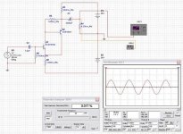
Another way to do this, which will generate more or less a JLH variant, is to combine two halfs of a JLH into one amp, one is NPN and another is PNP, to form a push-pull output stage,, without the use of a phase splitter.
I haven´t built nor tested it but PSpice says it should give 12Wrms into 6 ohms at 20Khz with less than 0,15% THD and +-15V supplies
I use 6 ohms because it represents better the true impedance of a 8 ohm driver
With 1.6A bias, idle dissipation is about 50W so efficiency approaches 25%
This kind of input stage needs lots of DC offset correction so a DC servo may be almost mandatory to make it work properly
I use 6 ohms because it represents better the true impedance of a 8 ohm driver
With 1.6A bias, idle dissipation is about 50W so efficiency approaches 25%
This kind of input stage needs lots of DC offset correction so a DC servo may be almost mandatory to make it work properly
Attachments
millwood said:here is the JLeph with a N-channel CCS.
I have not been able to get this circuitry to work with IRF devices at anything other than small power. The problem is that once the devices heat up, Vgs drops. and it doesn't matter which of devices sees the Vgs drop first, the end result is that there is a positive feedback between the two devices and it will cause both to overheat simutaneously. I have blown a few IRFs this way,
") .
.I looked at the Aleph schematics and they have V-I limiters on both devices so I may have to do that as well.
I guess the key is to figure out a mechanism whereby the Vgs drop in one device will not caused Vgs drop in another device.
maybe L-mosfets will work here without any V-I limiters.
Of my twenty some years of working with IRf devices, this is the first time that they actually die from over heating. You could actually see the Iq shot up and in a split second, the music stopped,
Yes, Mr. AmpMan, IRF mosfets do blow every once in a while,
at about 1w or so, this thing actually worked and worked quite well.
I haven´t built nor tested it but PSpice says it should give 12Wrms into 6 ohms at 20Khz with less than 0,15% THD and +-15V supplies
It's a standrd AB amp minus global feedback. Why not add the 2 transistor differential and be normal with gfb.
I've built simpler class A's with less comp's then your design, but will always lean towards ab class for ease and quality.
Easyamp said:
It's a standrd AB amp minus global feedback. Why not add the 2 transistor differential and be normal with gfb.
Not really, It's class A with complementary current sources instead of single ended, input impedance higher than 33K and something like 20dB of global feedback using only 4 transistors
Actually I see no point in building such an amplifier, but somebody was asking for simple bipolar/class A/high input impedance examples...
This design is almost exactly how we made low power amps in the 1960's. It is mostly a waste of time, as better circuit examples are well known and are not really any more expensive to make. Back in the 1960's, single supply operation was normal, and each transistor cost a significant amount of money, at the time. That is not the situation today.
not sure. I had them simulated to generate 4-5v peak. Which translates into 1w rms. You can presummably run it at higher gain (mine was set so that I could use those 12v bipin hologen bulbs as R1).
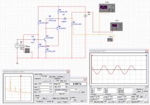
I have later changed it to a 2n5401 + IRF540 circuitry and use a little bit of negative feedback on the biasing circuitry as well: rather than tying R6 to the rail, it is tied to the output node.
This is essentially a SE amp (Q1). R3 and Q2 act like an "after burner" / current amplifier: R3 sense the output current and turns on Q2 to drive the output.
the "feedback" is provided by R2: as Q2 is turned on, it raises the voltage on Q1's emitter thus turning it off.
So it has the benefits of a traditional SE design, but has low Zout (because of R3/Q2).
I haven't breadboarded it yet, tho.
I have to say loud an clear "I LOVE THIS FORUM!"
Friends, "this is my beach!"... this is the subject i like and researching since 1960.
Love you all!!!
Very happy!
PMA the first
Eva the second
Millwood I third
Millwood II fourth
Steve Eddy fifth
Audio Geek sixth
Thank you all, my club, my people!........PMA, the one you show are working here WONDERFULL!!!
Regards all
Carlos
millwood said:btw, don't even think about using a mosfet as the input transistor: it is very sensitive to bias setting.
Why? I don't know.
I think it's because Mosfets have more Vgs drift versus
temperature and generally wander around more at low
currents. If you get the current up, they tend to stabilize.
simplest amplifier possible with bjt's
i am also planning to do some very simple class A design for personal computer.i require maximum of 3 watts output.
so i was searching in the net,i found your thread similar to my interest.recently i found a pdf file containing some circuits from the website ( http://www.rason.org/Projects/projects.htm )
could you please give some opnion about these circuits attached
Attachments
rmgvs said:simplest amplifier possible?
The question how to build the simplest possible amplifier using transistors intrigues me. I will report here my recent findings. To share the information with you and to hope for still further improvements.
Rudy
Rudy, Why don't you just keep it really simple and use a LM386 audio amplifier chip. uses 12V single sided pwr supply, and Zout is 8Ohms. you would be surprised at how loud this little device can be.
simple is better!!!!

yes, why not opamps
Cunningham,
indeed, why not. I recently built a preamp line stage using one 5532 opamp (circuit from mark hennessy) and the quality has really surprised me.
I think the gainclone-concept is along your lines of thought. I spoke to people who listened to the gainclone and its variants alongside known quality amps from Hiraga and the like, and the gainclone is okay but not of the same standard.
Rudy
rmgvs said:simplest amplifier possible?
The question how to build the simplest possible amplifier using transistors intrigues me. I will report here my recent findings. To share the information with you and to hope for still further improvements.
My design criteria were:
* output power no real issue, around 1-5 Watts RMS is okay (translates to: 5 Watts would be great).
* input impedance above 33kOhm, sensitivity of around 1 Volts RMS or higher.
* two gain stages max.
* no fets or mosfets, just BJT's.
* class-A
* single-ended
* no global feed back
After more than one month of listening, soldering, experimenting, I finished the result ending up with one of the first trials, leaving me with around one (1) Watt of power.
If only this design could be brought to about 5 Watts of output ...
Who wants to take over the fiddling from me, I think this is it for me at this moment given the design criteria...?
Rudy
Intersting challenge.
Simplest possible BJT class A - single end - 2 stages
- no global feedback
- no FET or MOSFET
What is first price, in this ....
- Status
- This old topic is closed. If you want to reopen this topic, contact a moderator using the "Report Post" button.
- Home
- Amplifiers
- Solid State
- simplest amplifier possible with BJT's?