PMA said:This one will be workable and will give reasonable output o several watts....
You should put input output at about 60-65% of V+
in this type of circuits.
For better Effiency.
Negative swing can NOT be more than 15/2= 7.5 volt
Positive swing will need to be 7.5 volt,
Leaves 7.5 volt over Transistor.
If we set output at 60%= 18 volt
gives 9 volt negative swing (8 ohm resistor & 8 ohm load in series)
Leaves 3 volt over transistor
at +-9 Volt output.
All these calculations based on 30V DC supply.
--------------------------------------------------------
30v/1.875A - In this case 7.5Vp= 3.51 Wrms/56.25= 6.24% eff
30v/2.250A - In this case 9.0Vp= 5.06 Wrms/67.50= 7.50% effiency
/halo -
") good at simple math - not necessary good amp designer
good at simple math - not necessary good amp designer 
additional schematics
In order to make this sample of circuits complete, here two extra circuits. They were designed/suggested to me by Geoff Moss in a discussion on these circuits (starting with the AR-3 headphone amplifier but built for normal speakers).
I have actually built these circuits and compared them with the original, but modified for 8 Ohms, AR3. These two circuits gave around 2 Watts RMS into 8 Ohms (the AR3 around 0,5 W under the same circumstances).
Strange enough, both these circuits did not fullfill my expectations on grounds of sound quality alone. I built all circuits using the same components (brands, types etc). They were good, but in the same league as the John Linsley Hood or Hiraga (and then I would suggest to build one of these). The AR3 however improves upon all of them (of course, subjective, but alas).
(pictures do not show in preview of supply!)
Attachments
Darlington Output?
Interesting to see a simple amplifier using Darlingtons. Years ago (about 15), I liked them because of their incredible gain and simplicity: I didn't need a driver transistor to saturate them.
Of interest: I was using them as switches for motorcycle headlight modulators. I liked being able to connect directly from a CMOS timing circuit directly to the output stage. Space was of the essence in a little potted package.
The burning question is this: how are they in an audio application? Sufficiently quiet and linear?
I'm all ears...
Bob
about Darlingtons & ME, halojoy
I tend to never use true darlington configuration.
If I need so much gain, I nearly almost use compl foldback, CFB.
And If I use one to drive another,
I do not connect the collector of the first one
to the second one's collector.
But instead I let the first transistor use
as much voltage C-E as possible, make use of all the voltage of the power supply.
And I never buy Darlingtons that are Ready made.
They mostly have resistors incorporated already,
and mostly the base of the output transistor
has no pin.
/halo
Hmmm
I'm suprised nobody got the idea....to use.....
IRON!!!!!!!
Used all the time in toobz, it allows all the power from the output to flow into the *speaker* and not be shared with a resistor.
100mH should be all that's needed for good LF, and one could even put a resistor in series for a softer bandwidth rolloff.
Check out my thread "Far be it for ... SS" for the last thing I breadboarded. Guess I'm now obliged to wind a 2A 100mH choke though..
Tim
I think iron went out of fashion at the end of the last century. Now it has been replaced by steel and aluminium. In any case, I'd think the purist would be better off investing in an aluminium heatsink to make a 2A CCS rather than winding copper around an anvil. Having said that Ciclotron has made an SE output amp using a big inductor; and I think this Vernesque machine suits his enthusiasm for "Metropolis" style.
On the topic of simple circuits I would like to introduce the idea of simplicity of concept rather than "as few transistors as possible". I think if you use too few devices their distortions can total more than using more devices in a more linear way. If I were trying to make a great sounding amp, without global feedback, I think I would simply use a cascade of common-emitter BJT stages, each with emitter degeneration to linearise each stage and to give each stage a current gain <1/10 that of the transistor. Have as many stages as needed until the final stage drives a 1-ohm resistor. Place the speaker across the 1-ohm resistor. It'll get hot. But no-one said it couldn't get hot. And never reference any voltages off the power rails - they are polluted.
The primary reason to use emitter-followers, or darlingtons to buffer the output is to reduce heat. With a 1-ohm output resistor a +/- 12V swing will burn 72W avg. With a CE buffer (say with a beta of 100) you can use a 100-ohm resistor and burn about 10W avg. But CE followers are not so linear and can be somewhat reactive and in some cases unstable.
Attempts to increase power without increasing distortion in that good-sounding 50 mW headphone amp (RudiStor AR3) are doomed and you don't have to do any tweaking to come to that conclusion. The first and the least important reason is power dissipation. The original version puts out 50 mW consuming 3 watts of power, that is about 1.7% efficiency. If you scale up everything to get 5W, the power consumption will be 300W. Indeed, as we learned, increasing output to .75W increased power consumption to over 30W. Even if you are not frustrated with an idea of building such a wasteful amp, there is a second reason why you cannot do it. This more powerful version will require more voltage swing from the first stage, which you cannot implement without sacrificing distortion figure, because of bad effects of Miller capacitance. So, no magic here, we are inevitably facing the problems we know all too well in matcing good performance and high power.
this can be it!
This thread in the solid state forum has been dead for quite a while now. Just recently there has been a publication on the net that may contain the amp am was searching for all the time:
http://www.redcircuits.com/Page80.htm
It seems to fullfill all of the design criteria I put in the first post. I will build this thing in due time but not in the very short run. I hope to meet other people in this forum who are open to experimentation and want to build this thing and are able to compare it to other good amps such as Zen, Hiraga, JLH etc.
Rudy
Re: this can be it!
really? does it have a global feedback loop?
what about just a simple SE amp using a darlinton and active loading?
rmgvs said:http://www.redcircuits.com/Page80.htm
It seems to fullfill all of the design criteria I put in the first post.
Rudy
really? does it have a global feedback loop?
what about just a simple SE amp using a darlinton and active loading?
maybe the difficulties with this whole effort is that the conditions are too stringent. For example, it would be hard to design an amp w/o global feedback to compete with amps that have global feedback (the Pass amps may be able to do that but they use mosfets, something you don't allow here).
with a few exceptions, the submitted schematics in this thread have global feedback.
so maybe if you can relax the conditions a little,
with a few exceptions, the submitted schematics in this thread have global feedback.
so maybe if you can relax the conditions a little,
I think the 8 Ohms resistor in each of these designs is a really stupid pitfall. It's a waste of power, and will really giuve you no good-effects, unless you want to replace it with 12V Automobile bulbs, to make the whole amp look like a simulated tube amplifier.
How about taking one transistor out of the small signal chain (as you don't really need it), and make a push-pull output or at least a current mirror i n the output instaed......
Circlotron ... You contribution is the most innovative in my opinion so far ......
How about taking one transistor out of the small signal chain (as you don't really need it), and make a push-pull output or at least a current mirror i n the output instaed......
Circlotron ... You contribution is the most innovative in my opinion
so far ......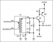
transformer input
Can you give some specifications and component indications for this design (where does it come from)?
The input-criteria (impedance and sensivity) come from the desire to be able to drive the amp straight from a cd-player and/or a highish output impedance tube pre-amplifier (that can not deliver any amount of current into low impedances: that's way the Zen amps can not be driven by simple tube-amps).
You have introduced a new element into this thread: the use of a transformer. I have nothing against it per se but these things are hard to find or very expensive or not sounding right..
Re: transformer input
I haven't given the all-BJT version a full workout (I've since abandoned it and opted for a JFET for Q1) so I presented it more as a conceptual circuit. But if you want to experiment, the component values are as follows (actually you can leave R3 out, I forgot to remove it from the schematic):
R1: 9.76k
R2: 39.2k
R4: 8 ohm, 50W
C1: 220pf
C2: 2,000-4,000uF 35V, non-polar
Q1: 2SC4793
Q2: 2SA1302
T1: Jensen JT-13K7-A
Ok. Kind of figured tubes were behind it somewhere.
Though even your garden variety NE5532 opamp can drive loads as low as 600 ohms so the 1.5k ohm input impedance of this circuit wouldn't be a problem for most any solid state source.
Well, "inexpensive" wasn't included in your design criteria so...
se
rmgvs said:Can you give some specifications and component indications for this design (where does it come from)?
I haven't given the all-BJT version a full workout (I've since abandoned it and opted for a JFET for Q1) so I presented it more as a conceptual circuit. But if you want to experiment, the component values are as follows (actually you can leave R3 out, I forgot to remove it from the schematic):
R1: 9.76k
R2: 39.2k
R4: 8 ohm, 50W
C1: 220pf
C2: 2,000-4,000uF 35V, non-polar
Q1: 2SC4793
Q2: 2SA1302
T1: Jensen JT-13K7-A
The input-criteria (impedance and sensivity) come from the desire to be able to drive the amp straight from a cd-player and/or a highish output impedance tube pre-amplifier (that can not deliver any amount of current into low impedances: that's way the Zen amps can not be driven by simple tube-amps).
Ok. Kind of figured tubes were behind it somewhere.
Though even your garden variety NE5532 opamp can drive loads as low as 600 ohms so the 1.5k ohm input impedance of this circuit wouldn't be a problem for most any solid state source.
You have introduced a new element into this thread: the use of a transformer. I have nothing against it per se but these things are hard to find or very expensive or not sounding right..
Well, "inexpensive" wasn't included in your design criteria so...
se
rmgvs:
since you seem to be interested in making an amp that sounds as good as the JLHs of the world, without global feedback, i would submit to you just the JLH without global feedback,.
it is identical to the JLH1969 (with four transistors, tho. But you can take out either the upper or lower output device if you truly want to make it a three transistor design). the only modifications: take out the lower feedback resistor (220ohm in the JLH design) and upside the DC blocking cap to as large as you can get (3300uf is good enough per my simulation). Here are some performance figures:
================================
JLH1969:
-3db: about 15khz;
gain: 750x;
THD: 0.79%
================================
If you a llow MOSFET, you can replace the output devices (2n3055x2) with MOSFET (I used irf540x2), and run the driver a little bit hotter (the 2.2k resistor on the phase splitter is downsized to 110ohm, as the lower resistor (560ohm down to 110ohm). Here is its performance for the MOSFET version:
================================
-3db: about 25khz;
gain: 2500;
THD: 0.53%
================================
Not bad, isn't?
since you seem to be interested in making an amp that sounds as good as the JLHs of the world, without global feedback, i would submit to you just the JLH without global feedback,
.it is identical to the JLH1969 (with four transistors, tho. But you can take out either the upper or lower output device if you truly want to make it a three transistor design). the only modifications: take out the lower feedback resistor (220ohm in the JLH design) and upside the DC blocking cap to as large as you can get (3300uf is good enough per my simulation). Here are some performance figures:
================================
JLH1969:
-3db: about 15khz;
gain: 750x;
THD: 0.79%
================================
If you a llow MOSFET, you can replace the output devices (2n3055x2) with MOSFET (I used irf540x2), and run the driver a little bit hotter (the 2.2k resistor on the phase splitter is downsized to 110ohm, as the lower resistor (560ohm down to 110ohm). Here is its performance for the MOSFET version:
================================
-3db: about 25khz;
gain: 2500;
THD: 0.53%
================================
Not bad, isn't?
jlh without feedback
Millwood,
thanks for the idea. In fact this idea crossed my mind before and I put a separate thread on the issue (JLH without feedback). I exchanged some ideas with Geoff Moss on this topic and he thought that the JLH without global feedback altogether would mean a complete redesign of the amp since the sensitivity is not workable and for some more points (see the thread).
Geoff thinks that a total amount of feedback comparable with that of the Hiraga is feasible though (to be continued). I have not heard of any people that fiddled with the amount of feedback in the JLH though.
Rudy
- Status
- This old topic is closed. If you want to reopen this topic, contact a moderator using the "Report Post" button.
- Home
- Amplifiers
- Solid State
- simplest amplifier possible with BJT's?