The reality check is also OK.
Good.
So OPAMP is lowering distortions in B-class bias setup.
I don't think so. The sound is not "clean", but enjoyable(I think I am fond of xover distortion)
 . With >100mA it becomes clean.
What, you supply the amp from a battery?
Precisely. 15000uF; 2 of them.

juz kiddin'
DC servo is realy not needed here at SSA. If you make all the steps correctly: hFE match, input BJT thermall joint and proper connections according to schematic, than you will get +/-10mV max offset variations below 1Hz, which is negligible.
Yup, that's how I like it.
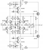
I'm afraid with this potentiometer on the gates of the power transistors and that the lengh of connections it suppose on printed board tend to some oscillations ? Too the driver's current has to be important in order to feed the gate capacitance at hight frequencies, right ? Can't be dangerous for the pot in case of failure ?I already made it in post #823 ...
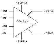
This negative input could be used on asymmetrical input amps amps to add a a 5Hz high pass Tension Feedback in order to make a servo with reasonable condensers values. Only need one or two resistances more and a cap.
Last edited:
Can't be dangerous for the pot in case of failure ?
Yes. Answer:- Bias Servo. One BJT and One more resistor. That's it. Problem solved.
Yes, thanks a lot. Yamaha had always produce some special ideas. I was amused by the four parallel BJTs, for mic's input...Did You check the link under INERESTING reading in post #832, don't miss it.
Last edited:
I'm afraid with this potentiometer on the gates of the power transistors and that the lengh of connections it suppose on printed board tend to some oscillations ? Too the driver's current has to be important in order to feed the gate capacitance at hight frequencies, right ? Can't be dangerous for the pot in case of failure ?
Look I prepared you some values. I'm sure that 15mA driver's current is sufficient not to allow outputs to oscillate.
This negative input could be used on asymmetrical input amps amps to add a a 5Hz high pass Tension Feedback in order to make a servo with reasonable condensers values. Only need one or two resistances more and a cap.
That would not cancel DC offset anymore than simple trimmer in sch cause the input stage has inherent offset variations which can be lowered only by separate DC servo. Please try to forget DC servo offset control here cause that is completely unnecessary by this design.
In SSA Balanced Input schematic I marked with * the parts needed for balanced version which can simply be omitted in unbalanced version, so very smooth transition.
Attachments
@ Lazy Cat,
Thank You for the balanced + L-Fet ver. of Yours SSA
You're welcome.
The best part of this design is the impedance match of both inputs, they are completely equal and still you can define global voltage gain by SSA current feedback to their emmiters, not affecting the input symmetry, all in the same differential/gain stage.
In SSA Balanced Input schematic I marked with * the parts needed for balanced version which can simply be omitted in unbalanced version, so very smooth transition.
So if we want to keep the possibility to feed with sym source we can place sym parts on pcb bord and let -in floting when asym use. If that very great stuff.
Marc

This wiill reduce it,i'm sure of that, when unbalanced input is requested (i know, you do not like that, but i t like some times to reduce the move of cones of Bass reflex drivers under their resonances frequencies):That would not cancel DC offset anymore than simple trimmer in sch cause the input stage has inherent offset variations which can be lowered only by separate DC servo.
That would not cancel DC offset anymore than simple trimmer in sch cause the input stage has inherent offset variations which can be lowered only by separate DC servo. Please try to forget DC servo offset control here cause that is completely unnecessary by this design.
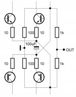
The 1k is unnecessary, just to protect the npn from short circuit of a power Fet. It will reduce the overall gain of DC to 1.1, instead of 1 if replaced by a strap. Without those somponents, the gain in DC is 10 with the proposed values by L.C. .
Nb: Following the PSU lines you use, so the power of your SSA amp, the CR resistances values (the overall gain of your amp) have to be set in order to get a full power for 1Vrms at the input. You can remove the 10k from the base of the NPN to the ground, and replace the 1K by 10k, as well.
Attachments
Last edited:
I appreciate your cooperation, you're wellcome, but please this is SSA thread and we are discovering implementations in accordance to SSA principle.
But it is SSA implementation, its the same design without cascodes. Out of curiosity I implementing those cascodes on a JLH headphone amp and although it did sound different it was not better, I prefer without but it will appeal to some.
Well, my proposal for a Board implementation would be using strap to give the choice: Symmetrical / Unsymetrical with DC comp and low pass filtering. With the cap value, filter will have a cutoff of 5hz with a 100k resistance, that you can change with the value of the 100k resistance. 47k will gives 10hz, 25k ->20hz etc, 33k->30hz. And you can forget to implant any of those if you don't want.
Attachments
Esperado I am glad to see that you are very interested in this un/balanced version cause it enables you customization to your needs.
Right now I am working on High Performance unbalanced version and I looks very promising, will report later.
At the same time I am thinking about the elegance of the later SSA balanced sch which is also very appealing to me to make it in near future.
Also all symmetrical differential input designs can be easily turned into full balanced version with global negative current feedback. A whole new space of an experimentation opened, me just love it.
Attachments
Last edited:
Member
Joined 2009
Paid Member
well I know which one I'm building but this thread moves too quickly for me, I can't keep any continuity in tracking my progress or else I just end up stuffing things into the thread that aren't relevant to the topic of the day - so I'm going to start a new thread (look for "TGM5").
So many options....which one to build?
Hi igor0203
First define your expectations than try to read from the start ...
I am sure you'll find something useful here, otherwise just interesting reading.
I'm going to start a new thread (look for "TGM5").
Stop-by sometime for sharing the info ... wish you successful built of your new amp.
I'm sorry for a fast developing thread, what can I do, ideas just pops out ... it will be a looong winter.
Last edited:
So many options....which one to build?
Although it was after a lot of development.
http://www.diyaudio.com/forums/solid-state/193923-simple-symetrical-amplifier-19.html#post2671499
It's a link to post 187.
OR
The attachment. See, ask LC, then choose.
Attachments
Last edited:
- Status
- This old topic is closed. If you want to reopen this topic, contact a moderator using the "Report Post" button.
- Home
- Amplifiers
- Solid State
- Simple Symetrical Amplifier