LC, I'm been searching through alot of website, the only good VAS transistor candidate are as below : 2SA1209/2SC2911, 2SA1360/2SC3423, 2SA1541/2SC3955
However, the source is from ebay, so i'm kinda risky of genuinity. Which one is better for VAS ?
About last time my destruction by spike/surge, only the Transistor are destroyed of positive portion. Negative is unharmed at all. 2 BC560C of Input and 2SA1707 for VAS, are either shorted or fused, one of them can see one piece chipped away from the transistor.
I want to ask upon your advise, that how to prevent such destruction. Does voltage regulation will safe them, by using resistor and zener only , or using 2N5401/2N5551 for cascode will do the job ? For input only, since VAS i'm going to change either one of them of above.
Try to catch 2SA1209/2SC2911, 2SA1360/2SC3423 or even 2SA1381/2SC3503. The problem is that these are mostly video CRT BJT-s, also suitable for VAS stages and their days are numbered till final expiration. I really don't know where to get them to be solid genuine, trial & error is probably the only method here.

There shouldn't be any spikes in the SSA circuit, since 15 V potentials are build-up slowly because of 1000 uF elcos charging characteristic (dV/dt). Bias currents in all SSA stages rising slowly just because of charging mechanism, so there's probably some other mistake present, to burn your BJT-s.
Last edited:
Look how busy lazy cat and boscoe (tssa) is!! They could not sleep as the ssa is spinning in there heads.
hehe....
You "lucky ba..." you are at least one step ahead
, poor me 
You're just
and say nothing, probably having a lot of fun 
 Andrej
Last edited:
If compare between those 3 pairs, which would be better ? (or I should buy tons of them for pile-stocking ^^)Try to catch 2SA1209/2SC2911, 2SA1360/2SC3423 or even 2SA1381/2SC3503. The problem is that these are mostly video CRT BJT-s, also suitable for VAS stages and their days are numbered till final expiration. I really don't know where to get them to be solid genuine, trial & error is probably the only method here.
There shouldn't be any spikes in the SSA circuit, since 15 V potentials are build-up slowly because of 1000 uF elcos charging characteristic (dV/dt). Bias currents in all SSA stages rising slowly just because of charging mechanism, so there's probably some other mistake present, to burn your BJT-s.
Yeah, I think I will go for 1360/3423, its from 'quite' reliable source i think. Its a e-bay online electronic store, and alot of promising trades it made.
About the spike, it isn't generated from the amplifier design. Its due to main power (240V AC) surge/spike, So it last only less than 0.1s, so it only over-volt positive side of power rail, thus destroying my positive transistor.
I'm getting better Vce transistor for VAS, but what about input stage ?
(does changing input cascode transistor to one of those above will prevent destruction ? or make use of regulated rail with zener is better ?)
You "lucky ba..." you are at least one step ahead
You're just
It was more the time of the Day (past midnight) you postet updates. !!!
That works but not quite in the desired direction. The even harmonics are reduced, but odd harmonics are at best unaffected or even increase.
I'll give the topology below a try.
Of course the triple output stage has now to be inverting.
Thats a interesting combination, does it work ???
BTW I think youre going in the wrong direction, dont try increase vas gain, rather keep it the same or even reduce it.
What you do is use a baxandall pair for vas, push pull like used by yamaha since 1980s. With this youll get below 10 ppm distortion at 1Khz and about 20 ppm at 20khz, this with triple output stage, the gain only around 45 db and openloop Fc close or exceeding 20khz. Performance can be further improved using emitter peaking techniques on the imput pair but then becomes more complex. As for compensation only additional low pass filter needed to raise gain margin which could be on the low side although phase should be around 90. This is without input cascode, the cascode will make stability very difficult to obtain but you can try. The input transistors have very low voltage swing accross them, so cascoding has little effect, the main contributer here is vas that has to supply all voltage gain. For just 6 transistors this kind of performance cant be beat.
Youll find this scheme used in a Jap amp (for Jap market only) of the early 2000s, ask them who designed it
Last edited:
I ahve not tested that yet beacause runnig to lots of simulations with even more difficult simulated speaker with passive crossovers I found that the EF output is less sensitive to
nasty low impedance with high phase shifts than the triple cascades. Although EF produces almost twice the thd it is more smooth with such loads. This becomes strikingly evident when the fb is grounded, no fb from the power stage. Thus follows compensation and such is easier with EF. No wonder that most commercial amps prefer EF.
Although I am weary of Spice models in this respect- the Gummel Poon model is very simple - I'll test now with model of thermaltrak BJT.
The EF works nice with the Vas op set to 40 mA .
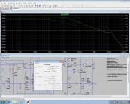
This is achieved by Vas at 24 V p out without fb at complex load
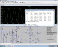
Fourier components of V(outvas)
DC component:1.20654
Harmonic Frequency Fourier Normalized Phase Normalized
Number [Hz] Component Component [degree] Phase [deg]
1 3.300e+02 2.455e+01 1.000e+00 -179.98° 0.00°
2 6.600e+02 5.630e-02 2.293e-03 -108.39° 71.59°
3 9.900e+02 6.281e-02 2.558e-03 168.17° 348.16°
4 1.320e+03 2.369e-03 9.650e-05 -170.86° 9.12°
5 1.650e+03 2.340e-03 9.529e-05 111.09° 291.07°
6 1.980e+03 1.257e-03 5.118e-05 176.13° 356.11°
7 2.310e+03 8.078e-04 3.290e-05 96.33° 276.31°
8 2.640e+03 6.874e-04 2.800e-05 145.42° 325.40°
9 2.970e+03 4.207e-04 1.713e-05 69.61° 249.60°
Total Harmonic Distortion: 0.343872%
the odd harmonics are still too high but anyway it can be achieved that this spectrum remains constant ( relatively) over the frequency range up to 15 khz and that is good.
The choice of the upper cascode BJTs has in the simulation no effect at all as long as VCEo is above 50 volts. However, and unexpected , the choice of the lower cascode BJTs has tremendous effect. I assume a problem with the Spice models is likely. It is hard to explain why small signal BJTs from Fairchild should perform much better then
from Motorola. I will use MPSA43 / 93 because I have a bag of these.
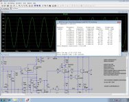
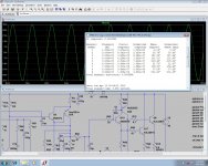
I ahve not tested that yet beacause runnig to lots of simulations with even more difficult simulated speaker with passive crossovers I found that the EF output is less sensitive to
nasty low impedance with high phase shifts than the triple cascades. Although EF produces almost twice the thd it is more smooth with such loads. This becomes strikingly evident when the fb is grounded, no fb from the power stage. Thus follows compensation and such is easier with EF. No wonder that most commercial amps prefer EF.
Although I am weary of Spice models in this respect- the Gummel Poon model is very simple - I'll test now with model of thermaltrak BJT.
The EF works nice with the Vas op set to 40 mA .
The input stage I mention will probably do 40 50 ppm distortion with only a EF. No more than 10 ma needed accross vas, 3 ma accross input transistor of baxandall pair.
The triple EF is less troublesome in real life than what simulators seem to suggest, try find a Jap amp not using them..........
I do not quite get what you mean could you provide a sort of schematic ( w/o values) ? To be clear what I mean is double EF instead of triple CFP. I think i will make a PCB for test imho the compensation and feedback must be optimized on a real device.The input stage I mention will probably do 40 50 ppm distortion with only a EF. No more than 10 ma needed accross vas, 3 ma accross input transistor of baxandall pair.
The triple EF is less troublesome in real life than what simulators seem to suggest, try find a Jap amp not using them..........
It was more the time of the Day (past midnight) you postet updates. !!!
Yeah I was busy testing CCS-s, many of them ...
Hey sonnya and MiiB, at which phase of an amp R&D are you? All the parts of schematic settled, confirmed and tested? Listening tests in progress? Please say something, since I'm very curious Lazy Cat.

Try to catch 2SA1209/2SC2911, 2SA1360/2SC3423 or even 2SA1381/2SC3503. The problem is that these are mostly video CRT BJT-s, also suitable for VAS stages and their days are numbered till final expiration. I really don't know where to get them to be solid genuine, trial & error is probably the only method here.
There shouldn't be any spikes in the SSA circuit, since 15 V potentials are build-up slowly because of 1000 uF elcos charging characteristic (dV/dt). Bias currents in all SSA stages rising slowly just because of charging mechanism, so there's probably some other mistake present, to burn your BJT-s.
Buy a lot.
I have purchased 5760pcs of KSC3503 and 5760pcs of KSA1381 in ESTU ...
Then they will produce them.
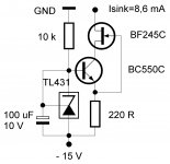
Today I rechecked BJT-J-FET CCS, because it was very late yesterday and maybe I missed something, but hey no, all parameters are the same. I put TL431 instead LT1034 plus BF245C instead 2N4393.
This CCS (also source version) has excelent DC and AC performance. From cold start to idle state, DC current change is only 20 uA max. Repeated AC tests showed no variation in Zout from DC to 100 kHz, noise voltage was less than 50 uV respectively to 8,6 V/1 kohm load, so better than -100 dB. With only six electronic parts this design is a must for audio purposes. Highly recommended!
This CCS (also source version) has excelent DC and AC performance. From cold start to idle state, DC current change is only 20 uA max. Repeated AC tests showed no variation in Zout from DC to 100 kHz, noise voltage was less than 50 uV respectively to 8,6 V/1 kohm load, so better than -100 dB. With only six electronic parts this design is a must for audio purposes. Highly recommended!
Attachments
I/we have an amplifier up running..I currently use it in our listening room...Must say the electronics's just a hobby of mine and there's no current plans for commercialization...I have for many years been building stuff and exploring things. Sonny and I are two different type of engineers. i com from the mechanical side of things and look at every thing like springs, dampers, friction and vibration. Sonny is very skilled engineer and he has a great tool box.. He made en SSA core thermally behave, I made quite a few things different in my take on the SSA. And I have kept on developing the circuit even further with the driven cascodes. The version I/we have playing sounds very good, but so does a few of the other amps I have heard.. Cant say if the good sound is founded in the SSA structure or in the things I have added/done differn't...but our old reference amp has retired for these 80W. The reason I got interested in the SSA was the close resemblance to the OLD Hiraga designs which were the marvels of that time. Here modernized and scaleable to higher power levels.
I/we have an amplifier up running..I currently use it in our listening room...Must say the electronics's just a hobby of mine and there's no current plans for commercialization...I have for many years been building stuff and exploring things. Sonny and I are two different type of engineers. i com from the mechanical side of things and look at every thing like springs, dampers, friction and vibration. Sonny is very skilled engineer and he has a great tool box.. He made en SSA core thermally behave, I made quite a few things different in my take on the SSA. And I have kept on developing the circuit even further with the driven cascodes. The version I/we have playing sounds very good, but so does a few of the other amps I have heard.. Cant say if the good sound is founded in the SSA structure or in the things I have added/done differn't...but our old reference amp has retired for these 80W. The reason I got interested in the SSA was the close resemblance to the OLD Hiraga designs which were the marvels of that time. Here modernized and scaleable to higher power levels.
Burmester integrated?
Hi Andrej.
I am not totally satisfied but it is mainly because of the idle current drift in SSA core.
Read this:
The TSSA core is much more stable in the idle current mainly because of the AC coupled feedback rather than DC coupled in the SSA.
The BC5XX input pair VBE drop changed 2mV/Celsius and has a thermal constant of 250degress/Watt.
So if the idle current is set to 2mA at time ZERO with a voltage drop of 15V you will get 30mW x 250C/W => temperature rise of 7.5 degress. Then the VBE drop with 15mV => 15mV less drop across 100R is 150uA more in the BC5XX.
In the TSSA we talk 15uA because of the AC coupling.
Hi MiiB
I appreciate a lot for this insight info, it is always refreshing to know more about a background of things happening, especially DIY audio fellows. Thank you very much.
... the old reference amp found its way to retirement, nice.
I appreciate a lot for this insight info, it is always refreshing to know more about a background of things happening, especially DIY audio fellows. Thank you very much.
I/we have an amplifier up running..I currently use it in our listening room...but our old reference amp has retired for these 80W. The reason I got interested in the SSA was the close resemblance to the OLD Hiraga designs which were the marvels of that time. Here modernized and scaleable to higher power levels.
... the old reference amp found its way to retirement, nice.
Hi Andrej.
I am not totally satisfied but it is mainly because of the idle current drift in SSA core.
Read this:
The TSSA core is much more stable in the idle current mainly because of the AC coupled feedback rather than DC coupled in the SSA.
...
In the TSSA we talk 15uA because of the AC coupling.
Yes, that's the main difference between two of them, latter is so much easier to settle and even doesn't need any CCS-s for proper bias conditions, only simple resistor and 1N4148 diode settling bias, plus compensates tempco drift of input BJT-s. What can I say, it cannot go easier than that - TSSA.
Nevertheless SSA has its charm to be DC coupled entirely and latter solution of cross NTC in FB bridge resolves tempco issue successfully.
I do not quite get what you mean could you provide a sort of schematic ( w/o values) ? To be clear what I mean is double EF instead of triple CFP. I think i will make a PCB for test imho the compensation and feedback must be optimized on a real device.
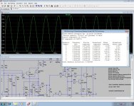
Ill just show the vas section put on the schematic as youve shown as Ive had a couple of other members ask for it but I am not at liberty to show all facets of the circuit. Keep values more or less as per schematic you have although they can be tweaked. In the commercial version Dc servo is used, improvement is made to the input section to extend frequency response, a triple output stage is used and different compensation method is used. Anyway here is performance charts with LTspice without the improvements as stated above. Commercial version just states THD as below .005 20hz -20 Khz at all powers below clipping.
Attachments
- Status
- This old topic is closed. If you want to reopen this topic, contact a moderator using the "Report Post" button.
- Home
- Amplifiers
- Solid State
- Simple Symetrical Amplifier