Hit the reply link in the lower right of the post.dumb question...how do I quote posts with this new format? ..can't find a button..??
Thanks for clarifying!There may have been a bit of crossing information.
I have an SSE using the GXSE18-8-5K OPTs as my main amp. It is a good choice. For wire I used strands of CAT5 for the input as suggested. For everything else I purchased some 600V hookup wire but did not need to use any. The leads on the various transformers are long enough that after trimming them for size I had plenty of wire left over to hookup everything else.Wow! good thing I waited until a total supply chain collapse to fulfill my dream of building my own system
I bought a couple of the IXYS parts on eBay so hopefully that works out!
This morning I pulled the trigger and ordered the GXSE15-8-5k output transformers you guys recommended.
I also ordered the Hammond Power transformer and choke as well as all the components for the PCB except the diodes, the coupling caps and the tubes and sockets- I'll sort that out this evening.
I'll prob go with these recommended diodes.
I suppose ill need some wire (duh) any recommendations there?
...
I want to do the classic box with a metal top plate- all the goodies organized on top. I’m a woodworker by trade so I’m looking forward to building a nice dovetailed walnut box for this thing. I saw George included instructions for this kind of layout.depending on how you want to house the amp
Nice....the typical way is to put all the tall stuff (or everything but the tube sockets) on the backside of the board. Then using short standoffs on the tube socket side of the board "hang" the board from the top plate. You can get aluminum from your local metal house in .125" or .093" thicknesses which works well with either a std 1/8" width table saw blade or a thin kerf blade if you want the top plate below the top edge of your wooden sides....or just top mount the deck with some screws.I want to do the classic box with a metal top plate- all the goodies organized on top. I’m a woodworker by trade so I’m looking forward to building a nice dovetailed walnut box for this thing. I saw George included instructions for this kind of layout.
Triple check everything that has polarity when mounting on the bottom of the board...it's a bit of a mirror puzzle and some things can get screwed up.
You need to allow for some ventilation, so either some holes or slots, or make the holes for the tube sockets a little oversized....and add some ventilation on the bottom panel as well.
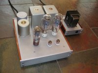
Here is a pic of my TSE.......you can see the four button head screws where the board is "hanging" from the top plate. I cleverly used the screw in the upper left corner to mount the fancy choke. ;-) The power transformer is an Edcor that I painted the end bells with some rattle-can hammertone rustoleum and used stainless screws and acorn nuts when I reassembled it.
...and there are some ventilation slots in the top plate between the transformers and the output tubes.
Attachments
This is the first SSE I built. Goodies on top.
Note that I am NOT a woodworker so I used stair nose molding to build my case. Including a goodly bit of "measure once, cut twice & it still don't fit."
The underside pic will give you an idea as to possible wiring. This SSE is set up as triode strapped with no cathode feedback. Please note that the A/C mains are not wired in & connected in the picture shown.
Looking at Tony's amp (and my amp) it's worth mentioning that you may want to source a motor run cap.........not required, but a nice addition.
.....the motor run caps are the large round cans shown on both Tony's amp and my amp. You can get them on ebay......or your local HVAC supply house.......the bigger the better. They optionally are wired in parallel with the last cap in the power supply, C2. If you want to do this you need a motor RUN cap not a motor START cap. These are typically paper-in-oil and they have a few properties that augment the ability of the power supply to provide current fast.
.....the motor run caps are the large round cans shown on both Tony's amp and my amp. You can get them on ebay......or your local HVAC supply house.......the bigger the better. They optionally are wired in parallel with the last cap in the power supply, C2. If you want to do this you need a motor RUN cap not a motor START cap. These are typically paper-in-oil and they have a few properties that augment the ability of the power supply to provide current fast.
Here is a pic of my TSE
This is the first SSE I built
These both look great! Definitely the look I'm interested in.
The photos of the guts are super helpful too.
it's worth mentioning that you may want to source a motor run cap
I figured those cylinders were the motor run caps! I don't really understand their benefits yet but I've seen a lot of talk about them on this forum. I'd definitely be interested in adding one to my build- ill have to do some more research...
I'm looking at IEC sockets now. Do you guys prefer the ones with built in fuse holders or without?
Would a 1.5amp (fast) fuse do the trick? I read somewhere on here that it should work.
I use an IEC with integral fuse & switch. It works & simplifies wiring.
2A slow-blo for the fuse.
There are many, many posts in this forum regarding motor run capacitors & they whys & wherefores of them.
This one by George (along with a few others) made much sense to me.
https://www.diyaudio.com/community/threads/electrolyticless-tubelab-simple-se.146880/#post-2149094
Besides, I think it looks cool & adds some balance. And aesthetics are a goodly part of why I do this
Great! thanks for the link- I'm gonna do some homeworkThis one by George (along with a few others) made much sense to me.
Thanks!Hit the reply link in the lower right of the post.
I added the recommended diodes to my order:
D1 and D2: https://www.digikey.com/en/products...-HFA08TB120-M3GI-ND/8269301?itemSeq=386970493
D3 and D4: https://www.digikey.com/en/products/detail/UF4007/UF4007CT-ND/965732?itemSeq=386979955
I was confused about them because there doesn't seem to be any specs part numbers supplied in the BOM for D3 and D4. Or maybe im just mixing something up.
Woodchuck: There is another member here (EvanC) that is a professional woodworker..and he's built some Tubelab amps.....his work may give you some inspiration....
Post #136 here:
https://www.diyaudio.com/community/threads/pictures-of-your-tubelab-amp.157491/page-7#post-2531984
..and as luck would have it my "under the hood" pic is post #133 on the same page....
Post #136 here:
https://www.diyaudio.com/community/threads/pictures-of-your-tubelab-amp.157491/page-7#post-2531984
..and as luck would have it my "under the hood" pic is post #133 on the same page....
They look correct to me.....buy a spare or two.......in case you let the smoke out of something when you mis-wire something. It sucks to have to re-order and wait.I added the recommended diodes to my order:
D1 and D2: https://www.digikey.com/en/products...-HFA08TB120-M3GI-ND/8269301?itemSeq=386970493
D3 and D4: https://www.digikey.com/en/products/detail/UF4007/UF4007CT-ND/965732?itemSeq=386979955
I was confused about them because there doesn't seem to be any specs part numbers supplied in the BOM for D3 and D4. Or maybe im just mixing something up.
Or have a bottle of this handy.They look correct to me.....buy a spare or two.......in case you let the smoke out of something when you mis-wire something. It sucks to have to re-order and wait.
Seriously. Spare a wee bit of budget for "just in case" on the solid state bits.
Ask me how I know.
wow! that one is crazy. I loved the curved edge
I can tell you guys are saving me a few headaches down the line.Seriously. Spare a wee bit of budget for "just in case" on the solid state bits.
Now I guess it's the waiting game! Lots of stuff in the mail right now and I'm getting excited about this project.
In the meantime I'll start thinking more about chassis design/layout, figure out the few other odds and ends (still haven't found the IEC socket/fuse holder knobs and switches) and learn more about how this thing works. Part of the fun of this project for me is learning how this stuff works!
Thanks again for all the very helpful guidance!
- Home
- More Vendors...
- Tubelab
- Simple Simple SE questions