Keep in mind that many transformer secondaries achieve optimum zeta=1.0 snubbing when Rs is 100 ohms or higher. The measuring instrument (oscilloscope + probes + cables) needs to have an input impedance at least a factor of 20X higher, to prevent it from disturbing the phenomenon under observation.
Conclusion: don't connect the "To_Scope" pins of your Quasimodo, to a 50 ohm terminator! No es bueno.
Conclusion: don't connect the "To_Scope" pins of your Quasimodo, to a 50 ohm terminator! No es bueno.
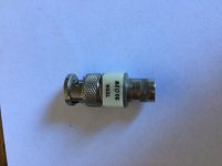
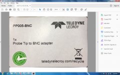
Hi all, thank you a lot for advises. The best way (for me) would be to buy such BNC to Scope 5mm Probe adapters, it’s BNC side must be male type with lock. If some of you saw that online with reasonable $, then please let me know. It is something like on attached image.

The Elenco adapter that came in the goodie bag with the Elenco scope probe, was a perfect fit for plugging the Elenco probe straight into a BNC male connector. Visually, the Elenco adapter looks very much like the PP-005 Teledyne LeCroy.
However, that adapter did NOT work with my Rigol RP3300 scope probe. The ground collar on the Rigol probe was a smaller diameter than the ground collar on the Elenco probe, so it didn't contact the adapter. That's bad. I guess every manufacturer of scope probes is completely free to design the mechanical dimensions of their probes and probe-adapters, however they like. There is no "standard" that all manufacturers must follow.
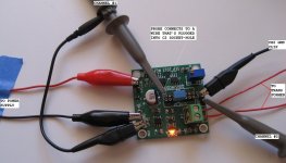
$5.00 to try the Teledyne LeCroy and find out whether it does or does not work for you, seems reasonable. If it works, you're done. If it doesn't work, you've only squandered five dollars. You can always take your Quasimodo PCB out of its enclosure, get rid of the BNC hardware, and perform your bellringer tests the same way that everybody else does: splayed out all over the kitchen table, with crocodile-clip jumper wires connecting it to the power supply and with scope probes attached to the metal pins sticking out of the PCB. Probe wires taped down to the tabletop to keep everything from sliding around. Notice the blue masking tape at the left of the attached photo. There's another piece of blue tape holding down the channel 1 probe wire at the top center [cropped out of the photo], and a third piece of blue tape holding down the channel 2 probe wire at bottom left [cropped out of the photo]. That's how we get things done.
However, that adapter did NOT work with my Rigol RP3300 scope probe. The ground collar on the Rigol probe was a smaller diameter than the ground collar on the Elenco probe, so it didn't contact the adapter. That's bad. I guess every manufacturer of scope probes is completely free to design the mechanical dimensions of their probes and probe-adapters, however they like. There is no "standard" that all manufacturers must follow.
$5.00 to try the Teledyne LeCroy and find out whether it does or does not work for you, seems reasonable. If it works, you're done. If it doesn't work, you've only squandered five dollars. You can always take your Quasimodo PCB out of its enclosure, get rid of the BNC hardware, and perform your bellringer tests the same way that everybody else does: splayed out all over the kitchen table, with crocodile-clip jumper wires connecting it to the power supply and with scope probes attached to the metal pins sticking out of the PCB. Probe wires taped down to the tabletop to keep everything from sliding around. Notice the blue masking tape at the left of the attached photo. There's another piece of blue tape holding down the channel 1 probe wire at the top center [cropped out of the photo], and a third piece of blue tape holding down the channel 2 probe wire at bottom left [cropped out of the photo]. That's how we get things done.
Attachments
.... Probe wires taped down to the tabletop to keep everything from sliding around....
I must admit this part has been annoying me. Rather than box it, though, I think I'll just mount it with stand-offs onto something heavy. Either a 1-1/2" block of dense wood or maybe a piece of 3/4" steel plate.
Extra points for a rubber jar-opener glued to the bottom....
The probe wires themselves are troublesome, they are uncooperative and obstinate. Their weight and stiffness cause them to torque the high hat and ground clip around to unwanted angles, where they either fall off, or short to adjacent pins. Solution: a penny's worth of blue tape.
Certainly you could bolt the Quasimodo PCB to a piece of 2x4 lumber, and glue non-slip rubber mat to the bottom of the wood. But the probes would still fight you.
Certainly you could bolt the Quasimodo PCB to a piece of 2x4 lumber, and glue non-slip rubber mat to the bottom of the wood. But the probes would still fight you.
Attachments
I boxed it due to same reasons as Jeff mentioned above. I placed two your testers in one enclosure: Quasimodo and trany phase swap identifier. No issue at all beside our finding what scope probe only must be used. No any static impedance jump cable... I could make some probe posts, but mistakenly decided to use female BNC in front panel. So, these two adapters will solve my case. Thank you.
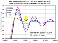
Below are charts of resent testing I've been doing with the Quasimodo. Transformer is an Antek AS-4218. Primaries and secondary not under test are shorted. Cx=10nf Cs=150nf. Quasimodo is running at 15Vdc.
First chart goes from Rs= 6Ω to 10Ω in 1Ω increments. These results now seem over damped to my untrained eye.
Second chart goes from Rs= 10Ω to 18Ω in 2Ω increments. These results seem more in the ballpark.
I used Rs=16Ω in the power supply I built for a FW F4 I built recently.
Others have reported (in the results thread) using Rs=18.3.
Assuming my testing procedure is giving accurate results, what Rs value would you choose for zeta = 1.
The great thing about "bell ringer" test jigs with snubbers is, that you can directly observe how well or how poorly this a specific snubbber setting actually works. If you like the waveshape you see, stop: yer done! If you don't like what you see, twirl the dial one way and then the other way, until you become happy. Then, stop: yer done!
I personally like to "sneak up" on a final setting by starting with the resistor setting too high (damping factor zeta much less than 1.0), and then reduce it while watching for the 2nd sinusoidal lumpy-bumpy to just barely go flat. As indicated by the yellow arrowhead in Figure 10, copied below. I like to overlay new traces on the same X-Y graph as old traces, to remind me what it used to look like versus what it looks like now. Not all scopes can do this, and the ones that can, sometimes make it clumsy. But I find the effort to read the manual and dink around with the knobs & menus, to be a good investment.
For those who worship precision (or don't trust their own eyeballs + instinct), the yes-math approach is available. Simply measure LT and CT using the method described in Appendix C and plotted in Figure 17. Then plug the appropriate quantities into Hagerman's snubber-design equations, linked in reference [1], and calculate Rs. If you wish you can dial your QM potentiometer to the calculated value and see what waveshapes Hagerman's calculation actually gives. Or you could just trust his math and not bother with a double-check in the lab.
_
Attachments
Short update: these BNC to Probe adapters from Mouser are fit Regol probes perfectly. I got two pieces. One was very tight first time and second was fine. Both made good connection.
PP005-BNC Teledyne LeCroy | Mouser
PP005-BNC Teledyne LeCroy | Mouser
Attachments
- Home
- Amplifiers
- Power Supplies
- Simple, no-math transformer snubber using Quasimodo test-jig