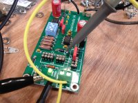
Got my Quasimodo up and running. I made one change others might be interested in: I bent a hook in D4's lower lead to form an attachment point for the trigger probe. (See attached picture. Mark will also be happy to note that I did indeed need the dip switches with my stone-age scope.)
I tested with a 100uH inductor and got 162kHz, which is right on the money from Mark's table. With that inductor I estimated zeta=1 at 110ohms, which seems quite a ways off (Mark's table shows 50ohms). I might run that test again, and see what's up.
I then ran it on the 6.3V filament and 200V B+ secondaries of an Edcor XPWR274 (as used in the Torpedo and Torpedo III). This was interesting as the two secondaries couldn't be more different.
I used the standard 10nF/150nF on the filament secondary and got Rs=22ohms.
The B+ secondary will have to make do with lower-valued caps (as they tend to grow in size when rated for 200V): I used 6.8nF/68nF and go an Rs=1Kohms.
Attachments
")
I tested with a 100uH inductor and got 162kHz, which is right on the money from Mark's table.
For those wondering: exactly which table that might be? It's an attachment to post #487 in this thread, dated 16 Nov 2014.
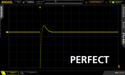
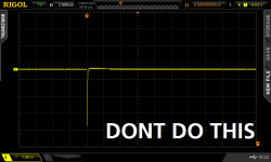
To see what "zeta=1.0" looks like, consult the Quasimodo design note Figures 10 and 11. You want to flatten out the second "hump" indicated by the arrow on Fig 10-11.
_
Attachments
Yeah, that was indeed my error. I ran things again and this time got 55ohms for 100uH (pretty much bang-on), and slightly different values for the others.
Torpedo III filament (6.3V)
Cx: 0.01uF
Cs: 0.15uF
Rs: 12ohms
Torpedo III B+ (200V)
Cx: 6,800pF
Cs: 0.068uF
Rs: 760ohms
Bottlehead SEX filament (6.3V)
Cx: 0.01uF
Cs: 0.1uF
Rs: 9ohms
Bottlehead SEX B+ (160V)
Cx: 0.01uF
Cs: 0.1uF
Rs: 400ohms
Torpedo III filament (6.3V)
Cx: 0.01uF
Cs: 0.15uF
Rs: 12ohms
Torpedo III B+ (200V)
Cx: 6,800pF
Cs: 0.068uF
Rs: 760ohms
Bottlehead SEX filament (6.3V)
Cx: 0.01uF
Cs: 0.1uF
Rs: 9ohms
Bottlehead SEX B+ (160V)
Cx: 0.01uF
Cs: 0.1uF
Rs: 400ohms
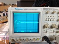
my stone-age scope.
Oh no, no, no. That is a wonderful machine for analog work. Count your blessings.
George
If I have a power supply where the are 4 Crectifier capacitors strapped accross each of the 4 rectifier diodes (aka Figure 8 page 6 of the quasimodo test jig manual). Then should each of the Crectifier be 1/4 of the value used for Cx_in_Quasimodo ?
Try putting that in LTSPICE simulation using the Cordell model of the 1N4004 diode (which will give you tons of ringing in simulation). Measure the oscillatory frequency of the ringing in transient analysis. You know L_oscillation, you measured f_oscillation, so you can calculate C_oscillation. Is C_oscillation equal to (yourcap/2)? Is it (1 x yourcap)? Is it (2 x yourcap)? Is it (4 x yourcap)? You'll have your answer and you'll get to experience the pleasure of finding things out (link)
Personally, I am not fond of capacitors across the rectifiers, and I generally remove them when I discover them in equipment I own.
Code:
* 1N4004C - copyright Cordell Audio November 23, 2010
.model 1N4004C D  (IS=500p RS=0.12 BV=400 IBV=5.00u
+ CJO=40p  M=0.35 N=1.6 TT=4u mfg=CA112310)
*So I'm trying to do a SPICE simulation to check my resistor wattage. Trouble is, I've never used SPICE before.
I drew up this:
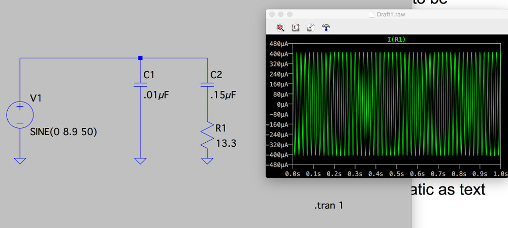
to model a 6.3V secondary (multiplied by 1.4) at 50Hz. Am I on the right track?
The simulation appears to show that my resistor is carrying 0.8mA, for a dissipation of about 7mW. Do I have the right end of the stick?
Thanks,
Jeff.
I drew up this:
to model a 6.3V secondary (multiplied by 1.4) at 50Hz. Am I on the right track?
The simulation appears to show that my resistor is carrying 0.8mA, for a dissipation of about 7mW. Do I have the right end of the stick?
Thanks,
Jeff.
Attachments

Wow, what a noob I'm proving to be. Missed the pp to pk conversion and the rms conversion.
But still, that seems like a minuscule value.
Without C2, the resistor would be dissipating nearly 1/2 a watt. Is the capacitor really good for a 500,000 factor reduction?
Thanks again,
Jeff.
But still, that seems like a minuscule value.
Without C2, the resistor would be dissipating nearly 1/2 a watt. Is the capacitor really good for a 500,000 factor reduction?
Thanks again,
Jeff.
the resistor is the snubber, it's what absorbs the ringing energy.
The capacitor is only there to allow the resistor to survive.
The impedance of the capacitor reduces the LF and DC currents down to a level that the resistor can pass without overheating.
The HF currents still pass, although slightly attenuated.
The ESR inside the capacitor will absorb some energy and will heat slightly.
Using a simulator comes AFTER you have learned how the circuit works.
You ask the simulator a question and it gives an answer to your question.
For that to be effective you need to know what question to ask and how to formulate that question.
Spice and similar simulation tools are not teaching aids.
You have to learn the circuit behaviour first.
You ask the simulator a question and it gives an answer to your question.
For that to be effective you need to know what question to ask and how to formulate that question.
Spice and similar simulation tools are not teaching aids.
You have to learn the circuit behaviour first.
I understand how the circuit works.
The question was an order-of-magnitude check: I expected the capacitor to limit the current through the resistor by 100x or 1000x, not 500,000x. Either my expectation was wrong, or I've done something wrong in the simulation. Thus my question.
Cheers,
Jeff.
The question was an order-of-magnitude check: I expected the capacitor to limit the current through the resistor by 100x or 1000x, not 500,000x. Either my expectation was wrong, or I've done something wrong in the simulation. Thus my question.
Cheers,
Jeff.
OK, second go at an order-of-magnitude check. Mark's PDF states:
so I ran the simulation again with 75Vrms and 50Ω, and got:For secondary voltages below approx. 75 volts RMS, and for typical snubber resistor values (50Ω < Rs < 500Ω), the average power dissipated in Rs will be less than 70 milliwatts.
4.7mApk
3.4mArms
58mW
So that checks out.3.4mArms
58mW
As a rude and sleazy "bodge" (a/k/a "kludge" a/k/a "shite-rig") you could get an approximate answer by calculating the capacitive reactance of snubber capacitor Cs at 50 Hz. Then you could hope and pray that you'll get a decent approximation of The Right Answer by considering Cs and Rs to be a series circuit of approximate resistances. Thus you assume Current =approx= Voltage / (Rs + Capacitive_Reactance).
Working a numerical example: if Voltage = 6.3V RMS, and if Rs = 13.3 ohms, and if Mains_Freq = 50 Hertz, and if Cs = 150 nanofarads,DO NOT FORGET: this is a greasy, slimy, offensively simplistic approximation, because it completely ignores the phase angles of the AC voltages and currents. It only happens to give a half decent answer in this one special case, because we have an unusual situation where (Capacitive_Reactance >>> Rs_resistance), and thus the influence of phase angles turns out to be quite small. We were lucky. I recommend LTSPICE simulation and using the little thermometer icon which plots power dissipated in a selected component. That method removes assumptions, approximations, and luck.
Working a numerical example: if Voltage = 6.3V RMS, and if Rs = 13.3 ohms, and if Mains_Freq = 50 Hertz, and if Cs = 150 nanofarads,
- Capacitive_Reactance = 1.0 / (2 * pi * Mains_Freq * Cs) =1/4.71E-5 = 21 Kohms
- Current = 6.3 / (13.3 + 21000) = 3.0E-4 amps = 300 uA
- Power dissipated in Rs = I*I*R = 1.2 microwatts
I noticed that some people have posted the C and R values for their transformer. Has anyone compiled this into a list somewhere?
I'm using an Antek AN-5220.
There have been a couple of attempts to set up public and/or privately curated tables of Quasimodo results, but none have really taken off.
Given the recent interest, I'm going to make a 3rd attempt with the lowest-possible-cost-of-entry: a diyAudio thread for results ONLY.
http://www.diyaudio.com/forums/power-supplies/313202-quasimodo-results.html#post5206650
If it gets a reasonable amount of traction, perhaps we can get it made sticky.
- Home
- Amplifiers
- Power Supplies
- Simple, no-math transformer snubber using Quasimodo test-jig