Remove the Capacitors across the diodes.
The Capacitors are NOT Snubbers.
The purpose of the caps across the diodes is to couple mains noise into your internal ground! I too had them in my earlyer linear supplies and was adviced to take them out.
Thanks both for the answers, I guess I can safely leave out those 220pFs.
Best regards.
As long as you have gone to the expense of dual bridges, etc., why not keep the ground returns from the ripple caps separated back to the bridges, and connect the grounds from the separate pos and neg sides only at the star ground on the right side?
The main reason for dual secondaries, bridges, and filters was: a lab bench power supply seldom sees equal current loads on Vout+ and Vout-. I estimate that ~ 95% of the time, it is operated as a unipolar supply, with a load on Vout+ and no load at all on Vout-. Had I opted for a single rectifier bridge and a center tapped transformer, DC would flow in the transformer secondary -- and I wanted to avoid that.
Fortunately, Triad Magnetics offers split bobbin EI core transformers (with much reduced RF coupling from primary to secondary), featuring dual independent secondaries. So I bought one of those, and also spent the extra money for two bridges, two off-board connectors, and two snubbers. About $3.00 additional parts cost plus an extra ~ 2 square inches of PCB area. I asked the end customer (me) whether that was an acceptable trade-off and got the answer: Yes.
You are correct that the KiCad circuit schematic, makes no effort to indicate the physical layout of the PCB grounding network. (relevant hyperlink).
since this offshoot chat is not about transformer snubbing or test jigs for optimizing snubbers, priority is low
An audiophile friend of mine strongly recommends the exotic CREE diodes, do they really make a difference in a design with a proper snubber.
I have not made any measurements on silicon carbide diodes, either with or without CRC snubbing networks, so I cannot offer an informed opinion. My uninformed opinions include (a) If you trust this audiophile friend of yours, why disregard his advice because of something as insignificant as mere money? (b) You could install silicon carbide diodes in some but not all of these audio devices, and then listen to them to find out whether you can detect a sonic improvement from putting SiC diodes in or leaving them out. Fortunately, diodes are physically large, easily manipulated devices; retrofitting diodes into equipment after a conclusive listening test, is relatively simple and straightforward. If you decide to add SiC diodes later, the swap won't be too painful.In fact my project is about building a few LPSes for my CAS chain (ARM computer, NAS, network switch, DDC ... etc) so it's indeed for audio use, and my question is whether the CREEs are worthy of their price tag, as I have to purchase 20 diodes the cost is rather important if CREEs are used.
As for MOSFET choice, I've given a recommended part number and two recommended substitutes in the BOM; plus a detailed list of specifications for choosing your own. After reading these, if you've chosen a MOSFET and if you think it ought to work, try it and see! You can always debug your board using a lab supply with the current-limit set very low (<15 mA). Dial up the voltage slowly and carefully: is your bellringer working? You can also follow the lead of member Karsten Sømand (in post #29), and just use a 9V battery. How much damage can a puny little battery actually cause?
I don't understand what you have concluded from your argument.The main reason for dual secondaries, bridges, and filters was: a lab bench power supply seldom sees equal current loads on Vout+ and Vout-. I estimate that ~ 95% of the time, it is operated as a unipolar supply, with a load on Vout+ and no load at all on Vout-. Had I opted for a single rectifier bridge and a center tapped transformer, DC would flow in the transformer secondary -- and I wanted to avoid that. .......
Why should DC flow in the transformer secondary of a centre tapped that is avoided by using a dual bridge rectifier solution?
since this offshoot chat is not about transformer snubbing or test jigs for optimizing snubbers, priority is low
If you have an analysis which shows that a CT transformer + single rectifier bridge, with unequal loads on Vout+ and Vout-, has zero DC current flowing in the secondary, Nelson Pass and Bob Cordell would be very interested to see it! Here's a passage from Cordell's power amp book on p.343; I put the relevant chunk in boldface type:I don't understand what you have concluded from your argument.
Why should DC flow in the transformer secondary of a centre tapped that is avoided by using a dual bridge rectifier solution?
Figure 16.1 shows a typical power supply for an audio power amplifier. In its simplest form it consists of a power transformer with a center-tapped secondary feeding a high-current bridge rectifier that produces positive and negative rails that are filtered by large reservoir capacitors. ...
An alternative arrangement employs two secondary windings and two bridge rectifiers as shown in Figure 16.2. One possible advantage to this design is that it avoids the circulation of direct current through the transformer windings when the positive and negative rail load currents are different. The flow of direct current throigh transformer windings (primary or secondary) should be avoided, as it can degrade transformer performance and sometimes create transformer buzzing. Toroid transformers are sometimes more sensitive to this effect than transformers of conventional construction.
Mark, I have acquired a function generator and an oscilloscope recently. Can I use them to find the value of R in the snubber without using the Quasimodo?
I was in the same situation myself, long before the Quasimodo concept occurred to me, long before I assembled the first QM prototype on solderless breadboard: I had a function generator. I had an oscilloscope. But I didn't have a Quasimodo.
I tried the measurement technique mentioned on page 5 of (Jim Hagerman's snubber paper), but the readings I got were not consistent.
I tried the impedance-vs-frequency sweep technique discussed in Morgan Jones's article "Rectifier Snubbing: Background and Best Practices", in Linear Audio Volume 5. (This is a hardcopy magazine that you pay money to purchase a physical copy; the articles are not free downloads). Again I got inconsistent readings.
However, don't let my lack of success discourage you. Maybe I'm a klutz. Maybe I performed the lab procedures incorrectly. Maybe my equipment was not working correctly. Maybe the transformers I was trying to measure were weird and worst-case "difficult" transformers, whereas you might be characterizing normal and "easy" transformers. Try it and see for yourself!
If it turns out that you don't succeed, worry not. You've got a Plan B. You can always slap together a quick-and-dirty bellringer test jig on solderless breadboard. The one I displayed in post #18 only took 2 hours to assemble, using parts that I already had in my junk box. When I saw how fantastically well it worked, that's when I decided to make a PCB version. So I could tear down my solderless breadboard and use it for subsequent projects! Another choice would have been, just buy another bloody protoboard. Keep Quasimodo as a permanent fixture on one protoboard, and use the second one for other projects. (BTW this would have been less expensive too: making PCBs costs more than buying protoboards.)
Last edited:
Mark, I have acquired a function generator and an oscilloscope recently. Can I use them to find the value of R in the snubber without using the Quasimodo?
If you're based in HK (from the location flag) and interested in the Quasimodo board, send me a PM. I'm printing a few with Seeed and should receive them after Chinese New Year, will have a few spare and can sell you one or two at cost.
I feel like I must be doing something wrong which is entirely possible as this is first use of my new and first scope. For a 160Va Triad Magnetics transformer, dual primary configured for 230V operation, 2 x 15V wired in parallel (10.66A @ 15V) I am getting a Rs figure of 13.5 Ohms.
I'm getting the right looking wave forms on both channel 1 and 2. Trigger settings are edge and trailing (down arrow). Everything looks right except the answer is nothing like anyone's that I've seen posted here.
(Actually I'm impressed that I managed to capture and save this jpeg.)
I'm getting the right looking wave forms on both channel 1 and 2. Trigger settings are edge and trailing (down arrow). Everything looks right except the answer is nothing like anyone's that I've seen posted here.
An externally hosted image should be here but it was not working when we last tested it.
(Actually I'm impressed that I managed to capture and save this jpeg.)
Last edited:
Connecting two secondaries in parallel will reduce inductance by a factor of 2, compared to operating the secondaries independently. As Quasimodo equation A.11 reminds you, the optimum snubber resistance is proportional to sqrt(Lsec); so the parallel connection reduces Rs by a factor of sqrt(2) = 1.414.I feel like I must be doing something wrong which is entirely possible as this is first use of my new and first scope. For a 160Va Triad Magnetics transformer, dual primary configured for 230V operation, 2 x 15V wired in parallel (10.66A @ 15V) I am getting a Rs figure of 13.5 Ohms.
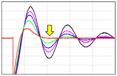
But I suspect a more likely explanation is: operator error. I think you have accidentally zoomed-in WAAAY too closely and are failing to see the big picture. I suggest that you snap a series of screen capture images just like the ones in (Post #143), showing your progress as you gradually dial the resistance down, and as you gradually sneak up on zeta=1.00.
Carefully note: the horizontal scale of the scope pictures in post 143 is 10 usec/division. Your scope photo seems to have been snapped at 1 usec/division ... i.e. your sweep was 10X too fast!
Remove Rs from its socket and adjust the horizontal sweep until you see 2.5 to 5.0 full sinusoidal periods of oscillation. You are trying to duplicate the first image in post 143. Snap photo #1. Now leave the sweep rate alone! Set Rs for its maximum possible resistance (~1K), put it in its socket, and snap photo#2. Keep dialling Rs down and taking photos, until the waveform's first sinusoidal trough flat-lines (yellow arrow in attachment). Leave the sweep rate alone! Check to see if you still read 13.5 ohms; I'm guessing you won't.
While you're checking for operator error, make sure you've actually plugged Cx=0.01uF and Cs=0.15uF into their sockets. Also make sure you have NOT accidentally selected "Bandwidth Limit" on either scope channel. Make sure you've switched the little switch on your probes to 10X, and make sure to tell your vertical channels the probes are 10X. An easy way to check this is with the probe calibrator on the lower right of the scope front panel. It ought to be about 2 volts, not 0.2v and not 20v.
Attachments
User error could be a distinct possibility!
Ok i was using the scope and probes on 1x and, yes, I had zoomed in but I had not missed the bigger picture. Here's infinity, 134R, 34.2R, 23.5R and 12.2R.
Ok i was using the scope and probes on 1x and, yes, I had zoomed in but I had not missed the bigger picture. Here's infinity, 134R, 34.2R, 23.5R and 12.2R.
An externally hosted image should be here but it was not working when we last tested it.
An externally hosted image should be here but it was not working when we last tested it.
An externally hosted image should be here but it was not working when we last tested it.
An externally hosted image should be here but it was not working when we last tested it.
An externally hosted image should be here but it was not working when we last tested it.
Last edited:
If the transformer with dual secondaries is wired as a centre tapped, does a single R+C snubber across the ~~ of the single bridge rectifier work as well as the snubbed dual secondaries?
I have not yet tested a C.T. transformer, but I will, and report back with my findings. It's worth reading Mark's documentation, where he points out that a C.T transformer still needs two snubbers;
(from the manual)The center tapped transformer (5th row) connects to the downstream power supply at three circuit nodes. It needs two snubbers: a first snubber between the top winding and the center-tap; and a second snubber between the bottom winding and the center tap.
Last edited:
I was in the same situation myself, long before the Quasimodo concept occurred to me, long before I assembled the first QM prototype on solderless breadboard: I had a function generator. I had an oscilloscope. But I didn't have a Quasimodo.
I tried the measurement technique mentioned on page 5 of (Jim Hagerman's snubber paper), but the readings I got were not consistent.
I tried the impedance-vs-frequency sweep technique discussed in Morgan Jones's article "Rectifier Snubbing: Background and Best Practices", in Linear Audio Volume 5. (This is a hardcopy magazine that you pay money to purchase a physical copy; the articles are not free downloads). Again I got inconsistent readings.
However, don't let my lack of success discourage you. Maybe I'm a klutz. Maybe I performed the lab procedures incorrectly. Maybe my equipment was not working correctly. Maybe the transformers I was trying to measure were weird and worst-case "difficult" transformers, whereas you might be characterizing normal and "easy" transformers. Try it and see for yourself!
If it turns out that you don't succeed, worry not. You've got a Plan B. You can always slap together a quick-and-dirty bellringer test jig on solderless breadboard. The one I displayed in post #18 only took 2 hours to assemble, using parts that I already had in my junk box. When I saw how fantastically well it worked, that's when I decided to make a PCB version. So I could tear down my solderless breadboard and use it for subsequent projects! Another choice would have been, just buy another bloody protoboard. Keep Quasimodo as a permanent fixture on one protoboard, and use the second one for other projects. (BTW this would have been less expensive too: making PCBs costs more than buying protoboards.)
Mark, thank you for your sharing.
My short cut is simply connecting the function generator --> C + Cs +R --> oscilloscope.
And see how does the damping change with different values of R. But, it seems that I have not taken the capacitance/inductance of the transformer into account.
Maybe, I need to eat the bullet and build a Quasimodo.
cwtim01,
pm sent.
Kudos for taking the measurements again and showing the results. They still look and feel wrong to me, severely wrong; so perhaps this will be a learning experience that gives me a Eureka Moment. Meanwhile would you please post the exact model number of the Triad 160VA transformer; I think I may want to purchase one that exactly matches yours, and duplicate your QM results that look and feel so severely wrong.User error could be a distinct possibility!
Ok i was using the scope and probes on 1x and, yes, I had zoomed in but I had not missed the bigger picture. Here's infinity, 134R, 34.2R, 23.5R and 12.2R.
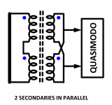
Please don't be insulted when I ask: did you verify the transformer's phase dots (Quasimodo design note Appendix D)? If you accidentally connected the primaries OR the secondaries with the phase dots wrong, the measured results will be unreliable. For a transformer with primaries in series (230VAC) and secondaries in parallel, the proper connection is shown below.
Attachments
- Home
- Amplifiers
- Power Supplies
- Simple, no-math transformer snubber using Quasimodo test-jig