I thought about swapping the heatsinks around and putting the modules on the other side. This puts the heatsink under the ventilation slots and puts a nice chunk of metal inbetween the toroids/psu and amps and more space between them, and keeps the signal and power wires further apart as well.
Requires more ventilation holes cut like this perhaps:
Richard is this what you meant by the idea in your email:?
It's a tight fit, but the heatsinks in this pic do have a larger footprint. I think this is what Jacco was referring to as well and the idea is growing on me. I'd get some new heatsinks with the same foorprint as the long ones in the pics above, but 100mm high for better chimney effect and black anodised which should all help I think.
Always looking forward to your suggestions...
An externally hosted image should be here but it was not working when we last tested it.
Requires more ventilation holes cut like this perhaps:
An externally hosted image should be here but it was not working when we last tested it.
Richard is this what you meant by the idea in your email:?
An externally hosted image should be here but it was not working when we last tested it.
It's a tight fit, but the heatsinks in this pic do have a larger footprint. I think this is what Jacco was referring to as well and the idea is growing on me. I'd get some new heatsinks with the same foorprint as the long ones in the pics above, but 100mm high for better chimney effect and black anodised which should all help I think.
Always looking forward to your suggestions...
Vikash said:referring to as well
Added bonus if you can size the heatsinks exactly to the inner height of the case:
- thermally coupling the heatsinks to the bottom and top of the case for additional cooling.
- transfering weight more evenly to the corners, instead of having it in the center.
- short wiring, the SKA likes that.
- possibility to seal the case, means no dust. I loathe dust in amps, shame i never fancied GoldyMundo
Dear Vikash,
That was exactly what I was referring to.
However, also consider mounting a sub panel to the sides as mentioned by Daniel and attach the amp modules to these, effectively removing the heatsinks.
The case will conduct the heat quite effectively, also no steel is used.
Regards,
Richard Krol
That was exactly what I was referring to.
However, also consider mounting a sub panel to the sides as mentioned by Daniel and attach the amp modules to these, effectively removing the heatsinks.
The case will conduct the heat quite effectively, also no steel is used.
Regards,
Richard Krol
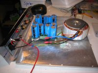
Thanks Jacco, I took to the points you outlined as they are quite appealing. This is the arrangement I have (pretty much) decided on. The sinks are SK416 114mm high (coupled to bottom and top of chassis). Thermal rating is 0.6K/W each. The sinks are slighly overlapped to cover the vents evenly, but the concern is that only ~60% of the sinks are vented.
I've turned the transformers around to create more space.
I'll *try* not to deliberate on this further, but please chip in if anything else comes to mind!
I've turned the transformers around to create more space.
I'll *try* not to deliberate on this further, but please chip in if anything else comes to mind!
An externally hosted image should be here but it was not working when we last tested it.
Vikash, that last one is perfect  but maybe you could make holes underneath bigger and completely evenly placed... it will be really effective, but ofcourse there will only come in what goes out...air, that is
Remember to have something isolating between upright trafo and chassis.... cork is nice
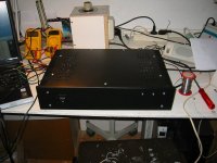
Ygdrasil, looks nice too ..... and nice workshop
but maybe you could make holes underneath bigger and completely evenly placed... it will be really effective, but ofcourse there will only come in what goes out...air, that isRemember to have something isolating between upright trafo and chassis.... cork is nice
Ygdrasil, looks nice too ..... and nice workshop


Another SKpre is born....
I don't know about anyone else, but finding a good pre has always been the biggest problem for me and have searched and tried heaps for years.
Several commercial pre's, passive, pre DIY kits and projects from opamp based, solid state, tube have been tried plus some of my own creations using opamps from the OPA2134 to OPA627 and all added either too much of their own flavour, veiled or were over blown. Most sounded good (some were just dreadful) but the presentation just wasn't right for my tastes or partnering equipment (modded CDP-X55ES, AKSA 55N+, Scan Speak OB / Vifa vented hybrid).
Recently I tried the SKpre and the best way I can describe it is having a pre without a pre. It's extremely neutral, natural sounding, adding very little of it's own flavour as far as I can tell. It seems to pass all the inner detail and everything else without hindrance or the veil that's common with a lot that I tried or heard. There's none of that fatiguing wow factor here, just good honest sound. Part may be due to the fact that there are no caps in the signal path but I'm sure it's all down to design, good power supply and implementation.
So for me, a happy camper with a pre kit for about the same price as a carton of cigarettes.... great value and a keeper.
GB150 D5, D6.... TO92 be gone.
I disliked the TO92 devices for D5, D6 on the GB150, as being an old engineer, I like a good solid mechanical mounting. I asked Greg for some other alternatives in a more suitable package and he came up with the BD139 (D6), BD140 (D5) which required R10, R12 to be changed to 1K1.
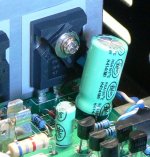
The change has been done and I much happier with using the TO126 devices. The base and collector were joined at the device, heatshrink added over the legs and joins, and the wires run to the top of the PCB to the - + locations. They were mounted on top of the Mosfets (Q11, Q14) and not on the heatsink. The amp has been tested all afternoon in the workshop with an ambient temperature of 28° and the heatsink didn't get over 50°C, so an increase of only 22°C. The bias didn't drift as much as before and stayed within a range of around 0.03V after the amp stabilised.
So far it's all good and I'll see how it fares over the next couple of weeks. I've added a pic showing the TO126 device on top of the mosfet and the blue and white wires going to the PCB.
I disliked the TO92 devices for D5, D6 on the GB150, as being an old engineer, I like a good solid mechanical mounting. I asked Greg for some other alternatives in a more suitable package and he came up with the BD139 (D6), BD140 (D5) which required R10, R12 to be changed to 1K1.
The change has been done and I much happier with using the TO126 devices. The base and collector were joined at the device, heatshrink added over the legs and joins, and the wires run to the top of the PCB to the - + locations. They were mounted on top of the Mosfets (Q11, Q14) and not on the heatsink. The amp has been tested all afternoon in the workshop with an ambient temperature of 28° and the heatsink didn't get over 50°C, so an increase of only 22°C. The bias didn't drift as much as before and stayed within a range of around 0.03V after the amp stabilised.
So far it's all good and I'll see how it fares over the next couple of weeks. I've added a pic showing the TO126 device on top of the mosfet and the blue and white wires going to the PCB.
Attachments
Just a quick note regarding the exceptional service that Greg Ball offers.
I made a mistake in connecting the amp to the PSU (Did not connect In E to PSU E)and it resulted in flames and smoke. Greg was very fast in responding to my e-mails and walked me through tests and repair procedures. This is exceptional service and much appreciated. Now that the problem has been corrected, Greg is supplying replacement parts at a very reasonable cost.
Thanks again Greg
This is the chassis I will use for my GB SKA150B monoblocks and the way I think of mounting ikn gthe chassis, Should I be concerned about the heat exposure to the caps ?
I have though of replacing one of the sides with the heatsink, but then it will not provide the shield between the powersupply and low voltage parts in the amp.
The heatsink is made from 3 pieces, but will be mounted together with a 3 mm copper sheet, to ensure the right thermal stability.
This is the special wound transformer I will use, it's 300VA and provides 2*22,5V, which should be perfect when running the amps as Class A amps.
See my DIY gear here: HIFI4ALL
and the way I think of mounting ikn gthe chassis, Should I be concerned about the heat exposure to the caps ?I have though of replacing one of the sides with the heatsink, but then it will not provide the shield between the powersupply and low voltage parts in the amp.
An externally hosted image should be here but it was not working when we last tested it.
The heatsink is made from 3 pieces, but will be mounted together with a 3 mm copper sheet, to ensure the right thermal stability.
An externally hosted image should be here but it was not working when we last tested it.
An externally hosted image should be here but it was not working when we last tested it.
An externally hosted image should be here but it was not working when we last tested it.
This is the special wound transformer I will use, it's 300VA and provides 2*22,5V, which should be perfect when running the amps as Class A amps.
An externally hosted image should be here but it was not working when we last tested it.
See my DIY gear here: HIFI4ALL
Hi,
I am guessing that you intend running +-31Vdc with Iq=1.5A
The dissipation will be around 30W per sink.
They will run hot.
They will cook everything inside that case, not just the caps.
I strongly suggest you put the sinks outside the case.
I think you also need to make them bigger.
Is that +-60mF of smoothing? That should be enough for 36W of ClassA.
But a 300VA transformer is cutting it a bit close. Keep in mind that a transformer feeding a capacitor input filter must be derated to about 70% of it's resistive rating.
The transformer becomes 210W effectively and you are asking it to provide half of that continuously just to meet the ClassA bias requirement. Then running it in a high ambient temperature.
Can I suggest you run at a bias of 500mA. This high bias will provide 8Wpk (4W) of ClassA and the four devices will cope with that quite well. It will still run hot but you may get away with those sinks and with lots of ventilation you might just get it to work internally as well.
Need help with components
Hi,
I`m waiting for my pair of GB300D, and now I wont to select the best components for power supply.
I think to use :
Bridge Rectifiers IXYS VBE 55-06N7
Caps -
Mundorf HC
Aerovox ALS30
Epcos B41456B9479M
Epcos SIKOREL
I`m going to use 33000 - 47000 uF per rail.
What is your suggestions about this stuff, witch cap`s are the best, and what you think about this Rectifiers ?
Re: GB150 D5, D6.... TO92 be gone.
Hi Rabbitz,
My GB150D is in transit. I'm interested in trying out your mod. Mounting the TO126 devise directly on top of the mosfet should result in better coupling and less lag. How is it performing now? Do you have the measurement before the mod is done?
rabbitz said:I disliked the TO92 devices for D5, D6 on the GB150, as being an old engineer, I like a good solid mechanical mounting. I asked Greg for some other alternatives in a more suitable package and he came up with the BD139 (D6), BD140 (D5) which required R10, R12 to be changed to 1K1.
The change has been done and I much happier with using the TO126 devices. The base and collector were joined at the device, heatshrink added over the legs and joins, and the wires run to the top of the PCB to the - + locations. They were mounted on top of the Mosfets (Q11, Q14) and not on the heatsink. The amp has been tested all afternoon in the workshop with an ambient temperature of 28° and the heatsink didn't get over 50°C, so an increase of only 22°C. The bias didn't drift as much as before and stayed within a range of around 0.03V after the amp stabilised.
So far it's all good and I'll see how it fares over the next couple of weeks. I've added a pic showing the TO126 device on top of the mosfet and the blue and white wires going to the PCB.
Hi Rabbitz,
My GB150D is in transit. I'm interested in trying out your mod. Mounting the TO126 devise directly on top of the mosfet should result in better coupling and less lag. How is it performing now? Do you have the measurement before the mod is done?
Hello Primetime,
I swapped the BD139's & BD140's into my 300D's about four days ago and am very happy with the results. I bolted them to Q16 & Q21 and moved the wire attachment point from bottom of board to top. The initial bias stabilzed much more quickly than before and, after monitoring the bias off and on for several hours under load, bias seems to stay spot on at 2.0v where before it would drift +/- .05v or more. Sorry, I've no temp. measurements but, they are certainly not running any warmer than before! HTH.
Gordy
Edit: Thank you Rabbitz and Greg for your help and input!
- Status
- This old topic is closed. If you want to reopen this topic, contact a moderator using the "Report Post" button.
- Home
- Amplifiers
- Solid State
- Simple Killer Amp Constructor Thread