jam said:Guys,
I agree that the shunt element is still part if the circuit but you all fail to see the point. Compared to a some sort of switched attenuator that that has multiple resistors in series with the signal path. If you don't believe me put a 10k resistor in series with the input of your preampl listen then put 10 1k resistors in series with the input of the same preamp and listen again.
Most of you like to comment but few seemed to have built and actually listened to the comparison. BAT a well known manufacturer as well as Pass Labs seem to concur and produce products with a similar setup.
To make it clear for you jam, I'm using fixed series resistor and switching shunt element (different setups in various attenuators, some are series, some are single resistors). For some reason you choose to argue about something. Can you tell me what is it exactly, as I'm missing your point again.
I also have APOX system, which I believe is closer to what BAT is talking about. Yet, transformer volume control seems to be working the best for me: no resistors at all
")
Peter,
The point that you fail to see is that regular resistors have end caps usually made of steel that hurt the sound , plus the wire and multiple interfaces....................please read the white paper and stop rambling on.
If you want the last word go for it, this debate has become mute at this point.................and why are you using a shunt?
You sometimes end up sticking both feet in your mouth.
Regards,
Jam
Attachments

jam said:The point that you fail to see is that regular resistors have end caps usually made of steel that hurt the sound , plus the wire and multiple interfaces....................please read the white paper and stop rambling on.
If you want the last word go for it, this debate has become mute at this point.................and why are you using a shunt?
Who told you I'm using regular resistors. I don't even get why the talk about end caps, it has nothing to do whith what is discussed here.
Why shouldn't I be using the shunt? It's the easiest approach to a good sounding attenuator, isn't it? I have 5 systems around, one of them uses it.
AMT-freak said:Aren't you both being a bit childish? Nothing wrong with children, though
Of course we are, and normally it shouldn't happen, but the past is haunting both of us.
Of course that shunt approach is the best, especially if you are using input buffer. What I was only suggesting, is that beside using a good resistor type for series element, you might also consider something better for shunt elements, as they almost equally affect the sonics, especially if you put them in series. To make it simpler and cheaper, I would tend to use a pot here.

Re the BAT whitepaper:
A. I wish they had said what the electronic switching elements actually were - J-FETs, opto-isolators, or what?
B. The comments about digital pots/volume controls agree with my prejudices but I wish there had been some measurement data as well. I tend to get suspicious when I see claims filled with audiophile adjectives plus a tendency to equate low cost with low quality.
C. The only thing wrong with motorized pots seemed to be that they were old fashioned.
sam9 said:B. The comments about digital pots/volume controls agree with my prejudices but I wish there had been some measurement data as well. I tend to get suspicious when I see claims filled with audiophile adjectives plus a tendency to equate low cost with low quality.
I stop'd reading when they said "low cost" -> "low quality" -> bad sound.
What happened to "let facts speak"?
Ok, I did some more work on this project last night, but have to stop now until next month.
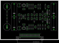
I will build the two channel's active circuitry on separate, small modules, which will be plugged into a mother board. The pot resides on the motherboard between the two modules, while the power supply stuff goes left and right of them. There will be a separate PCB for input switching and for the transformers and pre-regulators.
I will build a prototype version of one channel to experiment with the circuit a bit. Find below a preliminary PCB layout.
I decided to place a R-C-lowpass with Panasonic FC caps on each rail, accompanied by two Wima MKP-10 film capacitors.
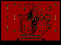
It is a double-sided PCB, but there are no vias and top side tracks are only placed where they can easily be accessed and soldered (e.g. on transistors and resistors).
I will build the two channel's active circuitry on separate, small modules, which will be plugged into a mother board. The pot resides on the motherboard between the two modules, while the power supply stuff goes left and right of them. There will be a separate PCB for input switching and for the transformers and pre-regulators.
I will build a prototype version of one channel to experiment with the circuit a bit. Find below a preliminary PCB layout.
I decided to place a R-C-lowpass with Panasonic FC caps on each rail, accompanied by two Wima MKP-10 film capacitors.
It is a double-sided PCB, but there are no vias and top side tracks are only placed where they can easily be accessed and soldered (e.g. on transistors and resistors).
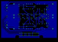
I'm using various PCB systems, the one I used for this project is Eagle from Cadsoft. There is a free evaluation version which is limited to a 100 x 80mm board size.
The rest is pretty straight forward: Laser print it to standard paper, make the paper transparent using cooking oil (sic!), light, develop, etch.
BTW, I'm using a special hydrochloride acid etching bath, but I'd like to have a "clearance" from a moderator before posting this.
The rest is pretty straight forward: Laser print it to standard paper, make the paper transparent using cooking oil (sic!), light, develop, etch.
BTW, I'm using a special hydrochloride acid etching bath, but I'd like to have a "clearance" from a moderator before posting this.
- Status
- This old topic is closed. If you want to reopen this topic, contact a moderator using the "Report Post" button.
- Home
- Amplifiers
- Solid State
- Simple discrete preamp