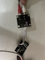
Hi Peet,I'm attaching the simple PCB I did to create a breakout board for A28/A31 modules. Consider this a beta and for testing only - my goal with this was to make it easier to work with the module vs having multiple wires all over the place. The LAN interface does work, but I'm not getting the LEDs to turn on, so if anyone has a suggestion on that I'd appreciate it.
Sorry but those lights are controlled by lan processor. They are not connected to any of the connections from the cable.
so in our case we need to know which of the i/o pin does that and which I/o pin is for Wi-Fi indication. The documentation does not cover it.
@partsexpress should really be giving input as to who supports the linkplay modules they are selling.
also they were selling a finished product under their name (PE) HI-Fly is they brand if I am not wrong.
Thanks @aditya - that explains a lot. Good news is that the LAN connection does work - just no indication on link & activity.
You are spot on with PE selling products using the modules, it's under the brand name Dayton Audio. I tried that avenue as well, but was told that they are completely separate companies and that they (Dayton) would not be able to help.
You are spot on with PE selling products using the modules, it's under the brand name Dayton Audio. I tried that avenue as well, but was told that they are completely separate companies and that they (Dayton) would not be able to help.

Hi Peet,Thanks @aditya - that explains a lot. Good news is that the LAN connection does work - just no indication on link & activity.
You are spot on with PE selling products using the modules, it's under the brand name Dayton Audio. I tried that avenue as well, but was told that they are completely separate companies and that they (Dayton) would not be able to help.
Happy to be able to add inputs
I don’t want to say this but it seems
PE is dumping stuff.
there are people who are able to hack the serial port but not sharing information
I am trying to see what input on serial triggers a acknowledgment on serial port.
while connected to serial I could only see single line out put for status
all the use full data was on the http API commands
I don’t know how much can code but I can read but can’t write.
@psmith001 and @npb1313
this is an interesting thread -
https://www.diyaudio.com/community/...mhz-oscillator-crystal-for-es9023-dac.376173/
this is an interesting thread -
https://www.diyaudio.com/community/...mhz-oscillator-crystal-for-es9023-dac.376173/
The modules can be configured as either slave or master. This is done in the firmware. I think the setting in the firmware that ships with the units is master.A reported issue with the A31 linkplay modules is that they operate as slave devices and do not generate the LRLCK and BCLK clocks. I didn’t see this mentioned here.
Is this everyone’s experience here?
Hi Peet,The modules can be configured as either slave or master. This is done in the firmware. I think the setting in the firmware that ships with the units is master.
I am unfortunately down with a stomach infection during the trip, so not been able to do much but is there any update from the guys at Linkplay?
I saw a thread that says ESS9023 works in Async mode but needs an external clock on the MCLK pin. Will try that but do not know if it will work or not.
Regards
Aditya
Hi @psmith001
Well that ref clock pin #37 didn’t work, I will see by giving it a pull up later in the weekend.
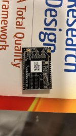
I currently tried a 50MHz txco connected as seen in the image and I have audio
infact the linkplay device announces “connected to your Wi-Fi” 😬.
During airplay the volume changes are sluggish. I feel the bass is a bit low but that might be the ESS9023 dac may be.
It is Arylic’s DAC board.
Well that ref clock pin #37 didn’t work, I will see by giving it a pull up later in the weekend.
I currently tried a 50MHz txco connected as seen in the image and I have audio
infact the linkplay device announces “connected to your Wi-Fi” 😬.
During airplay the volume changes are sluggish. I feel the bass is a bit low but that might be the ESS9023 dac may be.
It is Arylic’s DAC board.
Attachments
@aditya and @psmith001 I have no updates from my Linkplay inquiries either but this most recent update is good news for my purposes. I'm hoping to test switching the master/slave mode with my current setup (using the Adafruit UDA 1334A https://www.adafruit.com/product/3678) to see if that solves my issue and then I may just bite the bullet and move forward with an Arylic DAC
This the PCB i am working on for the adapter and need input from experienced builders.
the board has been divided for the chip as per my understanding of the digital and analog side, its a ES9023P.
i have kept the wifi module hanging a bit off as thats where the antenna are are located.
I will be running the module directly from 5volt and the 4 pin socket is Vcc Dgnd Rx TX
the connect on the lower left of the pcb is the analog supply of 5V, Agnd, Agnd , Right out and Agnd , Left out.
the Blue stuff is the bottom copper pour and red tracks are the top layer.
R9 and R10 will be 1uH inductors.
i know there would a lot of issues on this board so i m hoping for some constructive inputs to correct it.
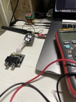
So I finally had time to test my board. Photo is attached here:

I'm able to successfully connect the A28 to wifi, can see the webpage at its IP and am sending successful GET requests. However, I have no audio out of my DAC. Everything is connected correctly and the DAC I'm using does not require MCLK, any thoughts as to potential issues?
Thanks!
I'm able to successfully connect the A28 to wifi, can see the webpage at its IP and am sending successful GET requests. However, I have no audio out of my DAC. Everything is connected correctly and the DAC I'm using does not require MCLK, any thoughts as to potential issues?
Thanks!
I think the volume for your DAC is controlled via I2C.So I finally had time to test my board. Photo is attached here:
View attachment 1084583
I'm able to successfully connect the A28 to wifi, can see the webpage at its IP and am sending successful GET requests. However, I have no audio out of my DAC. Everything is connected correctly and the DAC I'm using does not require MCLK, any thoughts as to potential issues?
Thanks!
Please check if your DAC is hardware mode compatible ie it will send out audio without configuring any registers
you could as Arduino control the DAC from I2C this is my assumption.
@aditya thanks for the reply!I think the volume for your DAC is controlled via I2C.
Please check if your DAC is hardware mode compatible ie it will send out audio without configuring any registers
you could as Arduino control the DAC from I2C this is my assumption.
I'm fairly confident that my DAC doesn't support I2C control at all. I've connected it to a Raspberry Pi Zero and successfully output audio using just the three WSEL, BCLK, and Data lines. I've linked the UDA1334A datasheet below:
https://cdn-shop.adafruit.com/product-files/3678/UDA1334ATS.pdf
I would recommend you try updating the Firmware on the board to work in slave mode - I sent you a pm.@aditya thanks for the reply!
I'm fairly confident that my DAC doesn't support I2C control at all. I've connected it to a Raspberry Pi Zero and successfully output audio using just the three WSEL, BCLK, and Data lines. I've linked the UDA1334A datasheet below:
https://cdn-shop.adafruit.com/product-files/3678/UDA1334ATS.pdf
Hi npb1313,@aditya thanks for the reply!
I'm fairly confident that my DAC doesn't support I2C control at all. I've connected it to a Raspberry Pi Zero and successfully output audio using just the three WSEL, BCLK, and Data lines. I've linked the UDA1334A datasheet below:
https://cdn-shop.adafruit.com/product-files/3678/UDA1334ATS.pdf
I jumped to the conclusion that it has i2c because of the SCLK marked pin on the top left of the image.
I apologize, I genuinely did not dig much deeper into the board you are using. - it was past midnight when I saw your post and was forcing myself to finish something that is still pending.
Hoping the PM from Peet has sorted the mystery.
@aditya no problem!! It was a fair suggestion, forced me to delve deeper into the UDA1334A datasheet which is never a bad thing!
@psmith001 Got your PM, will update on progress
@psmith001 Got your PM, will update on progress
@aditya no problem!! It was a fair suggestion, forced me to delve deeper into the UDA1334A datasheet which is never a bad thing!
@psmith001 Got your PM, will update on progress
The UDA1334A seems to be a similar chip to PCM5102 since it doesn’t need mclk where as the Arylic DaC chip ES9023 needed the 50MHz clock on the MCLK pin to work.@aditya no problem!! It was a fair suggestion, forced me to delve deeper into the UDA1334A datasheet which is never a bad thing!
@psmith001 Got your PM, will update on progress
Did you manage to change the firmware.
Just wanted to let you know that you won’t be able to access 10.10.10.254 web server with the new firmware
You need to download the Wiim app or iEAST app
Than connect your phone to the linkplay modules access point and launch the app from the phone
After which the app will ask for gps access ( iPhone ) I did only once and processed
Next you will see a searching thing and app will say found 1 device
Next click on the + button top right and select your 2.4ghz network and input the password
Once the pairing is fine and the module connects to the network you will hear “connected to your Wi-Fi network”
This voice prompt will be there every time you power on.
You can disable it via the api command = PromptDisable
UART is only output and song name will be available via API since UART is output only for debug. This is firmware dependent
Expect a few seconds of delay around 3 to 5 between for playing songs - this is what I am experiencing may be coz I do not have the second chip which is on your board
Attachments
Immediate success!!! @aditya and @psmith001 you both have saved me. It's a shame Parts Express isn't including the API documentation and the firmware tool when they sell these.
Now to remember what the heck I was going to do with the thing in the first place!
Now to remember what the heck I was going to do with the thing in the first place!
I am trying to piece together a document but will take a little timeImmediate success!!! @aditya and @psmith001 you both have saved me. It's a shame Parts Express isn't including the API documentation and the firmware tool when they sell these.
Now to remember what the heck I was going to do with the thing in the first place!
Happy to help 👍 but the main credit goes to @psmith001
Last edited:
- Home
- Source & Line
- Digital Line Level
- Simple DAC for LinkPlayA28/31