It took some time but I'm still here.
What has happened in the meantime?
I just worked on my amp when I switched off a fluorescent lamp. Unfortunately, the lamp has not suppressed and sent sharp transients into the power grid. Mostly only a crackling was heard, but not this one time. The MOSFETs have died instantly.
So I had to have install protection diodes in the circuit ... and troubleshoot my fluorescent lamp.
I've also improved the layout again. It is now smaller and the VAS has a thermal coupling.
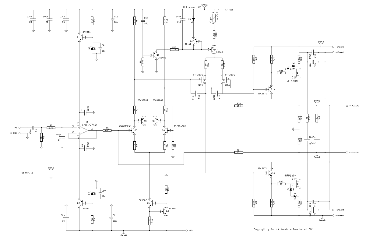
This is the final circuit:
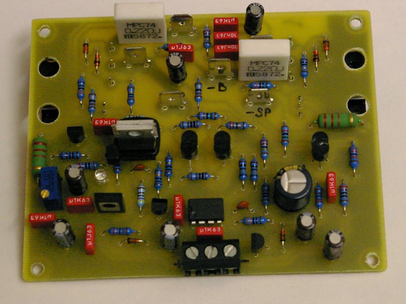
And this is the Board:
Also, I've changed some parts so I will use the stronger IRFP140N. And the power source for the first differential amplifier I have also changed. In the first cause because of the thermic coupling.
A detailed description can be found on my website. There are all documents.
Now I also have a name for this amp:
ZIRCLON140
What has happened in the meantime?
I just worked on my amp when I switched off a fluorescent lamp. Unfortunately, the lamp has not suppressed and sent sharp transients into the power grid. Mostly only a crackling was heard, but not this one time. The MOSFETs have died instantly.
So I had to have install protection diodes in the circuit ... and troubleshoot my fluorescent lamp.
I've also improved the layout again. It is now smaller and the VAS has a thermal coupling.
This is the final circuit:
And this is the Board:
Also, I've changed some parts so I will use the stronger IRFP140N. And the power source for the first differential amplifier I have also changed. In the first cause because of the thermic coupling.
A detailed description can be found on my website. There are all documents.
Now I also have a name for this amp:
ZIRCLON140
Always use protection diodes with every mosfet amp, even it is a drain follower, putting source on supply cause easely a transient killing the mosfet even as the 330 ohm resistor give it some protection, zeners of 8 volts are here far enough, how do it sound?
the mosfets U use are without diodes,
the mosfets U use are without diodes,
The diodes are build in. And against spikes at the gate there are Z-diodes (15V).the mosfets U use are without diodes
All I can say more, if the amplifier is ready. Unfortunately my speakers are not good enough. If the amplifier is ready, I'll drag it to a friend. He has very good speakers.how do it sound?
It is time to start my own speaker-project, the chassis gathering dust on the shelf.
The irfp140n has only diodes across source and drain, and not the gates where she are very important, you have also look at the supply if there exists spikes there are means to supress them also in supply, special resistors, diodes..
http://en.wikipedia.org/wiki/Transient_voltage_suppression_diode
I have made a H frame with martin sheets, I go now with big 18 inch and sell the 4 visatons because the qts is just to low for OB.
First H frame test with visaton wsp26s - YouTube
http://en.wikipedia.org/wiki/Transient_voltage_suppression_diode
I have made a H frame with martin sheets, I go now with big 18 inch and sell the 4 visatons because the qts is just to low for OB.
First H frame test with visaton wsp26s - YouTube
Last edited:
As far my Zirclon140 is ready
I've also heard him on ribbon speaker and I am delighted. Striking are the black bass and the spaciousness. High volumes do really fun, because the amp never sounds strained.
Here in the forum are some pictures from the construction.
I've also heard him on ribbon speaker and I am delighted. Striking are the black bass and the spaciousness. High volumes do really fun, because the amp never sounds strained.
Here in the forum are some pictures from the construction.
Maybe you are right, it is a buffer, maybe burr brown is also a good choice, you are right that in all equipment are op-amps, a self made opamp with jfets are also a possibility? but if it sound right for you then let it that way, that,s a important thing. if it is not broken, let it.
HI, thanks to your answer
Susy is SuperSymmetry like this :
http://nsm07.casimages.com/img/2012/01/26//1201260304001246339349624.jpg
http://img.photobucket.com/albums/v326/ftomto/Divers/xmodul0.gif
http://www.facstaff.bucknell.edu/esantane/movies/axschem.jpg
Susy is SuperSymmetry like this :
http://nsm07.casimages.com/img/2012/01/26//1201260304001246339349624.jpg
http://img.photobucket.com/albums/v326/ftomto/Divers/xmodul0.gif
http://www.facstaff.bucknell.edu/esantane/movies/axschem.jpg
Last edited:
I just found the scheme of Yamaha AS2100 and it seems that this is the same topology as yours
Yamaha A-S2100 Manual - Stereo Integrated Amplifier - HiFi Engine
Yamaha A-S2100 Manual - Stereo Integrated Amplifier - HiFi Engine
Hi moschfet,
In this thread, polyphaze use LTP with balanced CURRENT global feedback
http://www.diyaudio.com/forums/solid-state/270239-i-call-infinitron.html
In this thread, polyphaze use LTP with balanced CURRENT global feedback
http://www.diyaudio.com/forums/solid-state/270239-i-call-infinitron.html
Hi guys,
I want to show you this simple Circlotron circuit... The signal will be taken off from this circuit at the drain of the MOSFET. It is therefore a flawless transconductance amplifier.
Wrong assumption from the start. Circlotron is a unity coupled amplifier due to floating supplies, so it's not at all a transconductance amplifier. It is a different story if you were describing the interface between the driver and circlotron output stage, though.
Maybe, I can't see the manual without registration and I don't want.I just found the scheme of Yamaha AS2100 and it seems that this is the same topology as yours
Yamaha A-S2100 Manual - Stereo Integrated Amplifier - HiFi Engine
Also niceHi moschfet,
In this thread, polyphaze use LTP with balanced CURRENT global feedback
I Call it INFINITRON
I don't want to start a discussion here that does not help anyway.Wrong assumption from the start. Circlotron is a unity coupled amplifier due to floating supplies, so it's not at all a transconductance amplifier. It is a different story if you were describing the interface between the driver and circlotron output stage, though.
Wrong assumption?
Nevertheless, the amplifier works ...
I don't want to start a discussion here that does not help anyway.
Wrong assumption?
Nevertheless, the amplifier works ...
No argument there, it's just that the output stage is not a current-out stage per se, though within limits the input stage makes it so. Of course once the NFB loop is tied around it it has a very small output impedance - but it starts off with a small output impedance to begin with (so not a current source). If you look at the voltages of the gates of the output transistors, WRT GND you will see a gain of close to 2. This is actually one of the circlotron's virtues
back to the starting block
This was the initial idea of circlotron that I restart.
First I intended to have it in class A mode, but after analyzing the comparative distortion behavior with negative phase 3rd order harmonics , I found it more interesting to have it in class B.
With 4ohms load even the fifth gets negative reducing by this the loudspeaker's 3rd and 5th distortion, and expanding the dynamic.
Attachments
Hello moschfet , do you think it is possible to made an amplifier like yours with Jfet input and SUSY feedback ?
It is quite easy to build a simple two stage Jfet input and SUSY feedback circlotron.
I built several version of this back in 2004 and 2005. I know there are some threads here about my projects, but I guess the pictures are gone by now.
I can see if I can find any of my old circuits if it is of any interest.
Regards,
Johannes
the main disadvantage of hostarea, photobucket, imageshack and similar portals is the fact, that files will be delete after a certain time. Thus the files are only available within a time window of several months. If the files upload here, there isn't exist a time window for looking and download.Hi guys,
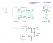
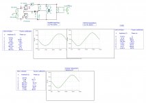
I want to show you this simple Circlotron circuit. In the simulation with LT-Spice it works very well. The signal will be taken off from this circuit at the drain of the MOSFET. It is therefore a flawless transconductance amplifier.
This is the circuit diagram:
An externally hosted image should be here but it was not working when we last tested it.
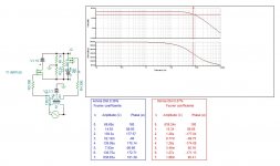
This is the FFT simulation:
An externally hosted image should be here but it was not working when we last tested it.
These are the frequency responses, open loop an closed loop.
An externally hosted image should be here but it was not working when we last tested it.
Ready to play
Thank you for upload the files here on this forum.
- Status
- This old topic is closed. If you want to reopen this topic, contact a moderator using the "Report Post" button.
- Home
- Amplifiers
- Solid State
- Simple Circlotron with power Mosfets