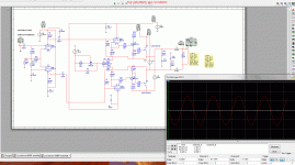
try a smal cap between the gate and drain or gate source, the oscillation come from the output mosfets, because it react on the idle current.
look at 330 pf it is on one site, give a phase shift, maybe you need also a cap on the upper part of amp, then use 150 pf each.
IRF510 change this for IRF610 and IRF 9610 change this for zvp4424.
look at earth leaks.
zobel network 10 n with 10 ohm each side.
most problem is the output mosfets, I do use a cap between drain and gate for the 2sk1058, I have blown them because of a oscillation, it did blow the gates even with protection diodes who are also defective.
regards
I have simulated it. Does not improve anything.try a smal cap between the gate and drain or gate source, the oscillation come from the output mosfets, because it react on the idle current.
It is already in therezobel network 10 n with 10 ohm each side.
I think, I will let it be like it is. The pulse is about 1.3µsec! No speaker in the world will respond.
And the amp is working very stable at complex resistance.
The quiescent current I also get slowly under control.
I would rather stay at IRF9610. It has been proven very useful in other audio circuits.IRF510 change this for IRF610 and IRF 9610 change this for zvp4424.
it can not be simulated
I do think that the simulation is meaningful within certain limits. Values were simulated down to the nanoscale. It shows me at least very clearly the direction in which the development goes.
As proof, I have tested them in real life ... as the simulation predicted
You cannot compare the circuits each other.I have them in the hybride without it oscillate very easy.
Problem with the lateral mosfets is that there is parasitic capacity the old cresendo and the kilowatter from elektor have them, in that time I have build it for a disco, I did need them with the 2sk135 and the 2sj50, it happens in the fet itselfs, a happy thing with circlotrons is that the both parts are of the same mosfets, make balancing very precisely, with the old mosfets the differences between P and N are also a reason to put a cap between drain and gate, I use a 39 pF cap with a 100 ohm carbon resistor from gate to null. cap to gate resistor to null, it is very stable afterwards and give no sonic penalty.
My design of a hybrid with a mu stage and mosfets dc coupled did not work well, if I connect the speakers it go puf puf puf, (motorboating) if not connected with a scoop it shows 100 volts PP without clipping, so I have to see the supply, I have make the transformer myself, maybe somewhere coupling, I have isolated the windings.
on a simulation it works perfectly, even witn a difficult load, there is some feedback on the supply if motorboating..
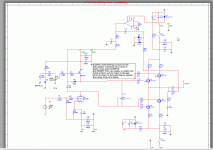
on a simulation it works perfectly, even witn a difficult load, there is some feedback on the supply if motorboating..

Last edited:
Hi kees
I don't understand your schematic.
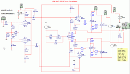
What is the circuit to Q1? A voltage source? Where is the anode resistance?
What are the funktion R12, 15, 21, 22 ? Source resistance?
@moschfet
can you please show me the actuel circuit? maybe I got a helping idea (the probability is low...but nobody knows)
I don't understand your schematic.
What is the circuit to Q1? A voltage source? Where is the anode resistance?
What are the funktion R12, 15, 21, 22 ? Source resistance?
@moschfet
can you please show me the actuel circuit? maybe I got a helping idea (the probability is low...but nobody knows)
Hi kees52,
I would build a hybrid also different. But anyway, this is a Circlotron thread
Hi lumu,
I still have a little problem. The offset voltage at the output is not constant. It moved slowly from about 5 mV to 50 mV.
Either I regulate it active, or I disconnect the DC in the feedback with capacitors. (100µF )
)
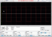
The bias is now relatively stable and the transient response of the square wave is also solved.
Here are some pictures:
1. 10kHz/ +/-10V/8ohm
2. 10kHz/ +/-10V/8ohm + 1µF
3 1kHz sinus clipping at +/-36V
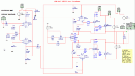
This is the current circuit. At least the most important thing. The buffer and soft start are not shown...
V2, V6 are LEDs
I would build a hybrid also different. But anyway, this is a Circlotron thread
Hi lumu,
I still have a little problem. The offset voltage at the output is not constant. It moved slowly from about 5 mV to 50 mV.
Either I regulate it active, or I disconnect the DC in the feedback with capacitors. (100µF
The bias is now relatively stable and the transient response of the square wave is also solved.
Here are some pictures:
An externally hosted image should be here but it was not working when we last tested it.
1. 10kHz/ +/-10V/8ohm
2. 10kHz/ +/-10V/8ohm + 1µF
3 1kHz sinus clipping at +/-36V
This is the current circuit. At least the most important thing. The buffer and soft start are not shown...
V2, V6 are LEDs
An externally hosted image should be here but it was not working when we last tested it.
Hi kees
I don't understand your schematic.
What is the circuit to Q1? A voltage source? Where is the anode resistance?
What are the funktion R12, 15, 21, 22 ? Source resistance?
@moschfet
can you please show me the actuel circuit? maybe I got a helping idea (the probability is low...but nobody knows)
Afcourse this don,t belong here, it is not a circlotron but a part of a new project what I have put here but must be a other place, so ignore it please.
this is what I did mean, see pictures what is a circlotron but not yet tested. I am happy now to be ready with a lab supply who have al the voltages I need, now just a case around it and ready.
see pictures of the circlotron, who already was here I believe.
but the motorboating hybride who has no cathodefollowers anymore was fun, puf puf puf, bradly resistors in the supple where the cause of it (to high impedance.
Your qour questions about Q1 it is a mustage who drives the gates, the source resistors are in my project in the source and not in the drain, it is because the schematic was already drawn that way, to let see why it did motorboated, but I like fishing so the motorboad works. the amp works now faulty resistors in supply.
for the moschfet circlotron, maybe thermal coupling wil help, irf9610 and the input, but if the offset is between puls and minus 100mv it is fine and u say 50 mv so that is more then satisfactory for me at least.
Attachments
Last edited:
Thanks 
why don't you make it active? It's the best solution.
that looks nice, but can you explain how do you fix the problem with the transients and the bias?
I want to learn or is it a secret?
why don't you make it active? It's the best solution.
If I remember correctly, you wanted to leave the transient probs? Why did you change your motivation?The bias is now relatively stable and the transient response of the square wave is also solved.
that looks nice, but can you explain how do you fix the problem with the transients and the bias?
I want to learn or is it a secret?

Because I have not enough space on the Board to place two opamps. I would need a complete new layout. And of course the amplifier should be simplewhy don't you make it active? It's the best solution.
This was a coincidence. I was playing with LT-spice to find the final frequency compensation. I started with the millercompensation, these are the capacitors at the VAS-mosfets (C1, C2 in latest circuit). The frequency response looked pretty good with 220pF in the simulation, so I try to make a simulation with a square signal. At the output were clean edges of the signalsIf I remember correctly, you wanted to leave the transient probs? Why did you change your motivation?
Then I tried to limit the frequency response with a capacitor (C3 in circuit #38)
There appeared suddenly my transient...
Q11 is mounted on a IRFP240 to regulate the bias. But it was to sensitive, the bias was decreasing too heavy. I replaced the diode with a LED(V6), so that the regulation range is smaller.
I hope it is understandable
I had kontakt with someone on the foon about circlotrons, he say this amps are always 100 procent feedback even without feedback loops...
What does that mean 100%? Impedance converter?
In my case, the signal is derived from the sources. So there occurs also a voltage gain.
A Circlotron certainly has a lot of advantages but not an automatic feedback.
Input and output have been compared in any way.
The IRFP240 have only a local current feedback.
The circuit is completed so far, the layout has been changed only slightly.
Here again the completely assembled circuit board. As a temporary heat sink is a 3mm aluminum plate.
An externally hosted image should be here but it was not working when we last tested it.
The layout:
An externally hosted image should be here but it was not working when we last tested it.
I will upload all complete files to reconstruction on my own page and link it then here.
Yes that is what I also tought, that man is not right, it is two single ended amps in balans.
I want to build the hybride circlotron some time, and look or it works oke, now I am busy with a hybride with two platefollowers and not cathodefollower as test. sound is very good but with feedback on I like it better (current feedback).
It looks very good your amp and also the pcb, I have to start with pcb making soon. what program do you use for pcb? I have ultiboard but the models and pads are very bad in multisim, as with many models in sim.
ThanksIt looks very good your amp and also the pcb, I have to start with pcb making soon. what program do you use for pcb?
I use KiCad, it is open source and it is easy to create your own symbols.
Hi Do you now that with a drainfollower special with the irfp240 your driver looks in 1275 pf each mosfet? and miller? therefore I do use sourcefollower this bootstrapping the capacitance and you see only the gate drain, and source drain capacitance who is very much lower. if you use drainfollower only a compound will work or use the 2sk1058 who has much lower capacitance of 700pF what is stil high.
you need a beefy driver for it if stay in drain follower configuration, I do not now how the impact is with circlotron.
what are the costs of irfp240? it is a nice one for this work, I will build after what I do now the circlotron with tubes afcourse (hybbride).
you need a beefy driver for it if stay in drain follower configuration, I do not now how the impact is with circlotron.
what are the costs of irfp240? it is a nice one for this work, I will build after what I do now the circlotron with tubes afcourse (hybbride).
Attachments
Yes I know that and this was a conscious decision. The 2SK1058 do not work so good as the IRFP240 in this circuit. At higher current the THD raises strong, I had noted that earlier.Hi Do you now that with a drainfollower special with the irfp240 your driver looks in 1275 pf each mosfet? and miller? therefore I do use sourcefollower this bootstrapping the capacitance and you see only the gate drain, and source drain capacitance who is very much lower. if you use drainfollower only a compound will work or use the 2sk1058 who has much lower capacitance of 700pF what is stil high.
Because of the capacity, it was easy to use the IRFP4310Z in this circuit without any problems.
This mosfet has 6860pF Ciss and 120nC Qg!
The IRFP240 is so cheap, that you can match it. About 1,20€ in Germany.
The IRFP240 is so cheap, that you can match it. About 1,20€ in Germany.
do you now a good components supplier in germany? who do not ask the big prise for shipping?.
If you use good drive it can be solved that is why I have also use a extra driver in de hybride circlotron. for the 2sk1058 better is to use it in source follower and maybe the irfp240 do better in drain follower configuration, and afcourse tho clean a amp it get clinic, so some distortion make it sound better special the first and thitrh harmonic.
- Status
- This old topic is closed. If you want to reopen this topic, contact a moderator using the "Report Post" button.
- Home
- Amplifiers
- Solid State
- Simple Circlotron with power Mosfets
