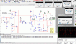
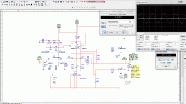
I did only simulate, the schematic of the circlotron is not tested with the irfp transistor, it loos promising, see the bandwith of it it touches 1Mhz, the faseflip is a problem with multisim, it behave very strange in windows 7 sometimes.
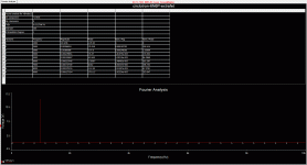
I test here the semisouth and the hexfet, last is less distortion, see distortion on last pic, .000 at high frequenties, so it can sound very good, this one I go testing later on, have to implement a offset servo because of tubes that is easy.
regards.
I test here the semisouth and the hexfet, last is less distortion, see distortion on last pic, .000 at high frequenties, so it can sound very good, this one I go testing later on, have to implement a offset servo because of tubes that is easy.
regards.
Attachments
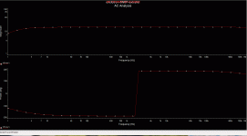
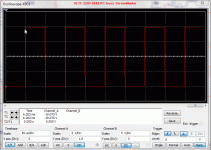
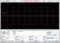
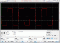
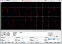
and some square waves, 10 Khz, 100Khz, 250Khz, and 500Khz.
not bad for tubes, but is it real? well, I have to measure in real, then we now.
not bad for tubes, but is it real? well, I have to measure in real, then we now.
Attachments
Last edited:
Thank you for your forbearance
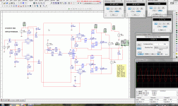
This is a version for fet-lovers and it works also with low distortions
An externally hosted image should be here but it was not working when we last tested it.
R23 is a pot for offset.
Good one, has current feedback, best in feedbackland, independence in bandwith and very high slew rate, only unstable in offset so tracking servo
is maybe needed, I don,t now with circlotron, but it is more needed.
some people has fear for voltage to the speaker, wel with a normal complementairy output you have also the same proplem as one mosfet fails, you have then als one voltage rail to your speaker coil.
circlotron can be made super balanced with all n fets or even only pfets or transistors.
have a ice evening.
No, this is voltage-feedback and it is driven in inverting mode ")
The advantages of inverting driving are lower common mode distortion and a virtual ground in the entrance. There is no ground-current and so the layout is less critical.
The buffer with the two jfets is needed because of the low impedance in the entrance.
The offset at the Speaker with a matched difference-amplifier is about 15mV.
No, this is voltage-feedback and it is driven in inverting mode
The advantages of inverting driving are lower common mode distortion and a virtual ground in the entrance. There is no ground-current and so the layout is less critical.
The buffer with the two jfets is needed because of the low impedance in the entrance.
The offset at the Speaker with a matched difference-amplifier is about 15mV.
ahh oke, yes now I see it, the first diff amp is voltage feedbacked, I was confused because I look to fast to the first two jfets.
I can drawn it en simulate, to see what it does.
Do you now kaneta amp. with this schematic I have use that idea, there is not much new possible in amp land, only combine these technics can give something new, best way to listen music is still live like a musicband without amplifiers.
This amplifier has voltage feedback, and bandwith and slewrate is a lot less then the hybrid circlotron version, but stil a joy to test it all.
.
regards
Attachments
Last edited:
Hi moschfet
this is my first post. I'm lookin for a amp that is not difficult to build. Nevertheless, it should sound good
I've build a chipamp with a LM3886 but I want a bit more power and it should be a discret one.
I've read silent with and I am very interested in the circuit, because I've heard the Thorenz TEM3200. Great cinema
It is possible to integrate a valve?
Are you posting on hifi-forum.de (bemos)?
Hello lumu,
welcome to the forum
welcome to the forum
The construction is relatively simple. Only the floating power supply you have to watch for the right connection. The best way is to label the board carefully.I'm lookin for a amp that is not difficult to build. Nevertheless, it should sound good
I cannot help in this point. That must you try out by yourself. At least I am thrilledNevertheless, it should sound good
I think that's a different caliber...I've read silent with and I am very interested in the circuit, because I've heard the Thorenz TEM3200.
Yes it would be possible. Only you would have to make the circuit from scratch. In addition, it is really expensive to match two triodes. But I would not like do that or plan it.It is possible to integrate a valve?
YesAre you posting on hifi-forum.de (bemos)?
ThanksNice work!
I cannot look in your headDo you think it's possible for me to construct a hybrid amp?
You must have an oscilloscope and to know how it works. Then LT-spice is very valuable tool to simulate your ideas.
The working method tends to produce errors. You must be very, very concentrated.I will build on hole grid because I haven't any plan to layout.
If you can wait a little bit, I will publish a working layout the next days...but only for transistors.
If you want to do it yourself then look for kicad or geda.
Sorry of courseI cannot look in your head
No I haven't a oszilloscope but I know LTspice. Thats don't mean that I realy know how to work with. But I will learn.
I just decide to wait for your Layout that seems to be the best way to start.
Can you show me a circuit how do you build the floating power supply and what kind of toroids ?
This is the power supply that I use and it works. You need two for stereo
The 225VA is a toroid and this is the floating power supply. I use 11mF per Voltage.
The 10VA is a print-typ for the driver. There I use 2 x 2,2mF.
You can put more capacity in both supply but it is not necessary.
An externally hosted image should be here but it was not working when we last tested it.
The 225VA is a toroid and this is the floating power supply. I use 11mF per Voltage.
The 10VA is a print-typ for the driver. There I use 2 x 2,2mF.
You can put more capacity in both supply but it is not necessary.
as I already thought is a circlotron the best way to get a precisely balanced amp, in a normal quasy amp with only Nfets there is always a sourcefollower and a drain follower who last one do amplify and so special ways has to be implemented for balancing, therefore I use a extra complentairy driver where the sourcefollower get a dreinfollower and vica versa.
a circlotron is only or drain follower or source follower, only need to switch voltage polarity, and so you have a amplifieing one or a follower one, that is nice for hybrides.
as soon if I am ready I go make a circlotron allfet who has current feedback, this is the best way for sublime audio amps.
a circlotron is only or drain follower or source follower, only need to switch voltage polarity, and so you have a amplifieing one or a follower one, that is nice for hybrides.
as soon if I am ready I go make a circlotron allfet who has current feedback, this is the best way for sublime audio amps.
Last edited:
Hi moschfet,
are you still working on your amp? I’ve already build the supply and now i waiting whats going on.
I've made a littel test (because waiting is boring) with 2 irf540 in the floating supply and it's amazing, you can hear music First i split the signal with a jfet in a symmetric and then i put it to the mosfets.
are you still working on your amp? I’ve already build the supply and now i waiting whats going on.
I've made a littel test (because waiting is boring) with 2 irf540 in the floating supply and it's amazing, you can hear music
First i split the signal with a jfet in a symmetric and then i put it to the mosfets.Hi lumu,
yes, I have just finished the second board and I am working at the fine-tuning.
I had a little problem with square-signal. The were a small overshot like a unstable behavior. But the circuit is very stable, so I wondering what it means.
Now I discovered the problem. It is the negative feedback. When I use a coil in series to the measuring resistance, the square is clean.
In the meantime, I built a PC for measurement. There is the sound card QUARTET of infrasonic build in. So I can run my microphone with 48V phantom power directly and do not need a separate microphone amplifier.
Sorry, when I am so slow, but I want to present a really good amp. And I incidentally have a Job and my other hobby sport...
I see that you can employ yourself usefulI've made a littel test (because waiting is boring) with 2 irf540 in the floating supply and it's amazing, you can hear music First i split the signal with a jfet in a symmetric and then i put it to the mosfets.
paralelliing a capacitor over the feedback resistors will remove overshoots, make value so that overshoot is barely visible. amp overshoot is like a fast car, if it hit the breaks it not stops a la minute.
your amp is fast, so, try, both parts afcourse as the ciclotron has two parts out of fase.
see posts 63 here how fast a hybride is, a allfet or bjt hybride is even faster.
your amp is fast, so, try, both parts afcourse as the ciclotron has two parts out of fase.
see posts 63 here how fast a hybride is, a allfet or bjt hybride is even faster.
Hi kees52,
it is strange the overshoot appears until approximately 10V at the sense resistor.
You can easily drive a load of 1μF/8ohm.
In complementary amplifiers, the capacitor is often the root of all evil. I usually tried to avoid him. When complex loads are driven it can easily lead to phase problems.
But I give them a try because the simulation looks very good and at the measured resistance, it seems to work well ...
it is strange the overshoot appears until approximately 10V at the sense resistor.
You can easily drive a load of 1μF/8ohm.
In complementary amplifiers, the capacitor is often the root of all evil. I usually tried to avoid him. When complex loads are driven it can easily lead to phase problems.
But I give them a try
because the simulation looks very good and at the measured resistance, it seems to work well ...My fears have been borne out. I took two capacitors with 22pF respectively.
If I increase the quiescent current the amplifier starts to oscillate. It is listen into the tweeter as a bright overlaid 100Hz hum. Using the oscilloscope, you watch the high-frequency components.
Next, I will replace the IRF9610 with 2SA1930.
Moreover, the quiescent current is not stable. It sinks during the operation. I am trying to find a more stable compensation.
The construction still requires some attention
- Status
- This old topic is closed. If you want to reopen this topic, contact a moderator using the "Report Post" button.
- Home
- Amplifiers
- Solid State
- Simple Circlotron with power Mosfets