Cost difference wasn't much between 5 and 15 PCB's. So i ordered 16 ") .
.
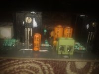
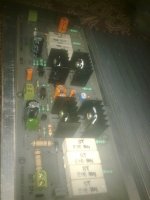
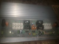
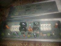
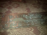
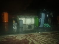
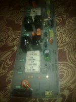
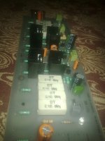
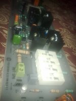
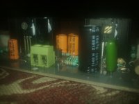
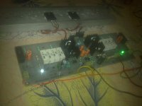
Populated the first board.
Again many thanks to Alex mm, without his support it wont had been possible.
Any advice on power transistors mounting and drilling holes.
Regards,
Aniket
.Populated the first board.
Again many thanks to Alex mm, without his support it wont had been possible.
Any advice on power transistors mounting and drilling holes.
Regards,
Aniket
Attachments
-
 190520131591.jpg287.4 KB · Views: 367
 -
 190520131608.jpg407.4 KB · Views: 144
 -
 190520131607.jpg404.5 KB · Views: 142
 -
 190520131605.jpg471.5 KB · Views: 131
 -
 190520131598.jpg447.1 KB · Views: 96
 -
 190520131597.jpg258.1 KB · Views: 82
 -
 190520131596.jpg400.3 KB · Views: 271
 -
 190520131594.jpg346.9 KB · Views: 309
 -
 190520131593.jpg320.2 KB · Views: 318
 -
 190520131592.jpg295.7 KB · Views: 321
Easy does it.
I certainly wish well Aniket and his project, but experience has taught me that until one hears it do music, you literally NEVER know. It could be theoretically perfect and yet sound poor, or theoretically junk yet still sound fantastic.
It's also quite possible that Mk.1 is no big deal, but Mk.3 may come alive. One lives and one learns.
I suggest you add a 470Ω resistor in series with the base of Q4, this will improve the performance with the amplifier driven into a clip.
Q4 from this diagram:
http://www.diyaudio.com/forums/attachments/solid-state/348129d1368337244-simple-100w-power-amp-250w-hifi.jpg
Also see the same resistor properly implemented on this diagram:
http://www.diyaudio.com/forums/attachments/solid-state/328299d1360046931-simple-100w-power-amp-2n3773.jpg
For existing boards I would either cut a trace and insert it, or pull the base lead out of the board and insert it.
I regret not having spoken earlier.
"the addition of R8, which prevents the reference voltage from collapsing when Q4 saturates during a negative clip, improving the recovery time."
Nelson Pass A40
https://www.passdiy.com/project/amplifiers/the-pass-a-40-power-amplifier
Last edited:
Success!!
Hi all,
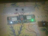
We could hear some music now.
With a few glitches initially, amp worked fantastic.
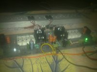
Used a +/-17V supply, a single pair of output tansistors and a 50W 4 ohm coaxial speaker for testing.
On first power up, with no load and input, the output shows 16V !!!.. The 2n5551 and 5401 turned out to be fake or maybe the pinout reversed, it depends on the manufacturer maybe. In many datasheets it's E-B-C for 5551 and 5401 and pinout is reversed for BC's. I would buy new 5551/5401 from a different make.
Then i replaced the LTP, CCS and current mirror with BC556 and BC546, inserted a 470R resistor between the base of Q4 as suggested. and
Output shows -2mV DC offset, is this normal, the negative DC offset.??
So, the amp worked great with BC556/546 in the input section. Set the bias at 50mA. Measured the current through LTP, shows 0.74mA for each transistor. measured the VAS current through R6(82R), shows 6.2mA, fine.
Connected the speaker, dead quite, no humm and no hiss, silent.then, connected an audio source(my phone) and crystal clear sound.
Impressions of the sound:
Bass was awesome, great depth and punch, you can say tight!! great thump at the lower end (30~60Hz). Highs were crisp and open specially the upper end of the vocals at about 10k frequency range. Mids were very smooth and clear, I am happy, certainly the best amp i have heard till now. I am excited, how well it will sound with +/-56V supply and my main speakers.
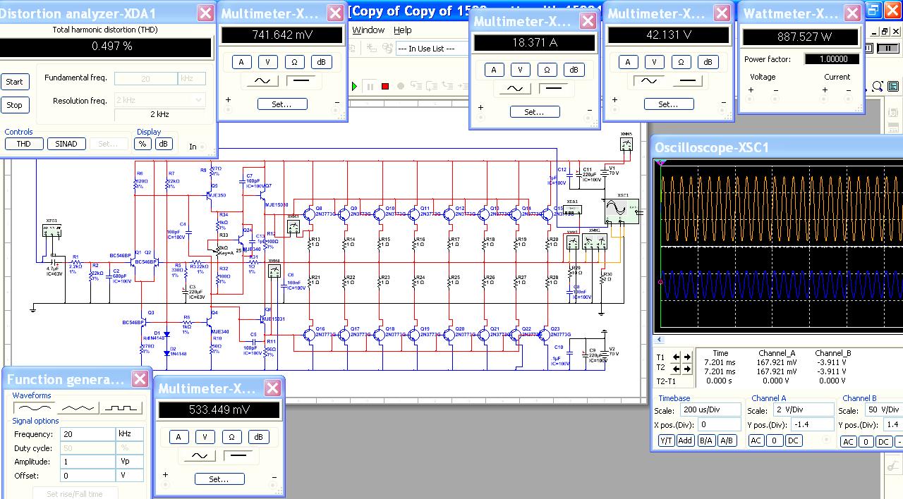
A thumps Up for multisim, the simulation results are very close to the actual circuit, a very good and eay to use simulator, i recommend it.
Many thanks to everyone who have helped and taught me through this, and not to forget Alex mm, without whom i could not build this amp.
Thanks Again
Regards,
Aniket
Hi all,
We could hear some music now.
With a few glitches initially, amp worked fantastic.
Used a +/-17V supply, a single pair of output tansistors and a 50W 4 ohm coaxial speaker for testing.
On first power up, with no load and input, the output shows 16V !!!.
. The 2n5551 and 5401 turned out to be fake or maybe the pinout reversed, it depends on the manufacturer maybe. In many datasheets it's E-B-C for 5551 and 5401 and pinout is reversed for BC's. I would buy new 5551/5401 from a different make.Then i replaced the LTP, CCS and current mirror with BC556 and BC546, inserted a 470R resistor between the base of Q4 as suggested. and
Output shows -2mV DC offset, is this normal, the negative DC offset.??
So, the amp worked great with BC556/546 in the input section. Set the bias at 50mA. Measured the current through LTP, shows 0.74mA for each transistor. measured the VAS current through R6(82R), shows 6.2mA, fine.
Connected the speaker, dead quite, no humm and no hiss, silent.then, connected an audio source(my phone) and crystal clear sound.
Impressions of the sound:
Bass was awesome, great depth and punch, you can say tight!! great thump at the lower end (30~60Hz). Highs were crisp and open specially the upper end of the vocals at about 10k frequency range. Mids were very smooth and clear, I am happy, certainly the best amp i have heard till now. I am excited, how well it will sound with +/-56V supply and my main speakers.
A thumps Up for multisim, the simulation results are very close to the actual circuit, a very good and eay to use simulator, i recommend it.
Many thanks to everyone who have helped and taught me through this, and not to forget Alex mm, without whom i could not build this amp.
Thanks Again
Regards,
Aniket
Attachments
I had a hunch it would sound good . +/- 56 V is exactly what I use on my amps as it suits 63V caps . DC offset is excellent if -2mV . I dare say you can run it directly from a CD player ? If wanting a very cheap preamp the old NAD 3020 is a good workhorse . I always can listen to music if friends use the NAD .
Well done . Tell us more when fully working .
Well done . Tell us more when fully working .
Thanks Nigel,
I would make Rod Elliott's P97 preamp, and would use a switch to bypass the tone control. whole amp would be an integrated amp. also i have a 5 band and 10 band eq. otherwise.
Hi ilimzn,
the schematic on page 1 is history, it has been modded and upgraded severely.
Regards,
Aniket
I would make Rod Elliott's P97 preamp, and would use a switch to bypass the tone control. whole amp would be an integrated amp. also i have a 5 band and 10 band eq. otherwise.
Hi ilimzn,
the schematic on page 1 is history, it has been modded and upgraded severely.
Regards,
Aniket
Rod Elliot , a hero . El Cheapo amp is a gem . This is typical Elliot .
IMD - Something New
This site also .
A Paul Kemble web page - Mission Cyrus 1 integrated amplifier.
IMD - Something New
This site also .
A Paul Kemble web page - Mission Cyrus 1 integrated amplifier.
it would be very helpful to go back to post1 and add in an index to the current sch and other useful links to important information.........
the schematic on page 1 is history, it has been modded and upgraded severely.
.......t
I thought so . Even allowing for the simplicity of the program I imagine there is truth in it . That's what you hope to see . Maybe someone who has analyzed it in a different program will say if they know differently ?
I will stick my neck out and say this amp should outperform many super amps of the 1980's . Ones which get good money on ebay . The trait I look for is the ability to be a low power amplifier when required .
I will stick my neck out and say this amp should outperform many super amps of the 1980's . Ones which get good money on ebay . The trait I look for is the ability to be a low power amplifier when required .
@ Aniket, Nigel
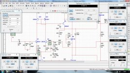
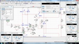
The program shown is Multisim, the same I have been using for 11 years now and swear by it.
Overall, it's nothing to write home about, it's main redeeming point being that its simulator is outstanding. Better yet, it is very conservative. If it says something will do say 500 kHz, in real life it will do better than that, like 520...550 kHz. If it says THD is say 0.01%, actual THD will be less, like 0.008% or some such.
Obviously, it's up to the user to properly define real world part tolerances, which surprisingly few people do.
Trust it Aniket, it deserves your trust. If there are discrepancies, more often than not you will find it was you actually, not the program. Very often, power amp THD is higher in real life than in the simulation, but that almost always happens because a loudspeaker is more complex than a simple lab resistor. The more complex the speaker, the greater the deviation from simulation, but that's only to be expected.
The easy way out is to search the Internet and find the electrical schematics of loudspeaker crossovers. Then simply make the nominal Ohmic value have a tolerance of say +/- 15%, which can happen once the speaker drivers start to heat up. This should give you a more realistic idea of THD.
It's a great result for something some would have written off as a muscle amp .I don't use simulation , I love to see spectrum analyzer graphs ( real ones ) . The analogy here is running a big engine in top gear at the lowest speed possible . With big well designed amps we can go to 0 and still have refinement . My guess is 90% of the critical evaluation will be 0 to 1 watt . When people say wow that sounds good it will be the 0 to 1 watt . Openness , depth , sweetness , speed . 220 uF 63 V low Z next to each power transistor is a thought ( Panasonic FC perhaps ) .
As the amp gets louder it is punch and speed people like . That is the power supply mostly . Big transformer and enough capacitance ( not too much capacitance , a friend said such amps are muscle bound and sound slow ) . 22 000 uf ? 100 W per rail / channel Dvv set as a rule on another thread . I would say that's fine if the transformer is large enough . If it is too small I think the sound will be bloated . Changing the input coupling cap can rescue that ( less bass ) . Truth is less PSU capacitance also will help . One idea is to double up transformers and then double again when money permits . A 1000 VA amp can be run on 500 VA . It will usually be able to clip on real music at it's peak voltage without PSU sag . At 2000 VA it should be able to give sustained sine-wave power . I always assume real life class B to give 50% of the PSU potential . If using a switch-mode PSU perhaps 64% . My friend John designs amps with switch-mode because it gets him through certification more easily ( cheaply ) . The switch-mode designer has already paid for the tests . My friend says nothing his amp does changes that . The reason this matters is that big amps tend to take power on the crest of the mains waveform . This will often result in compatibility problems as laid down in regulations . No one can argue with my friends reason to do it . Some say switch-mode sounds better ( they said that of CD ) . I have doubts when class AB .
Another thing . If running a 1000 VA amp give it a > 32 amp mains supply . It will tighten the sound . If stereo 2 x 32 A . In the UK just run 2 ring mains with just one double socket to each . Very cheap to do . It will use 2.5 mm cable which in ring has about 54 A capacity ( 32 A fuse ) . All PA guys use large cables .
I did say it then, and I'll say it again - I believe 99.9% of living room listeners will never need more than 100W/8 Ohms. I do believe that is true.
As for transformers, I think a good rule of thumb is to use as many transformer VA as you want watts coming out of the amp on a continuous basis,times 1.25 for reserve. Say you want a 100/200W into 8/4 Ohms - according to my view, you would need 250 VA (300VA being the nearest standard value) PER CHANNEL. If it's one transformer feeding both sides, add another 15% to cater for channel differences, use a 600 VA transformer. More will not hurt.
On PSU filter caps. Larger value caps dofilter better, letting less junk pass, but are naturally slower than the same type half the size. The somewhat obvious solution: use both in parallel, the larger, say 10,000uF, for better filtering, and the smaller, say 4,700 uF for improved speed.
Sony has been doing just that for the last 25 years.
- Status
- This old topic is closed. If you want to reopen this topic, contact a moderator using the "Report Post" button.
- Home
- Amplifiers
- Solid State
- Simple 100W power amp