I m gonna buy a custom made 42-0-42V, 15A sec transformer(1250VA). I already have 8 10000uF63V capacitors, so 40000uF per rail, would this be enough for 2*250W continous RMS power.
Regards,
Aniket
Depends.
42-0-42 under zero load, or under full nominal load? because if under full nominal load, in the small signal domain the supply will rise by its tolerance. Assume just 3% difference, and in the small signal part your supply lines could be producing +/- 59V. That's close to the caps' 63V rating, really close. Nothing should happen, but make sure about the difference at no load and full load on.
Using 20,000 uF per supply line per channel should, according to my math, be good enough for around 31 Joules per channel. We typically need 1-2 Joules of energy per every 10W of dissipated power, depending on how complex (difficult) that load is. So, you have more than enough energy stored for your target 250W/4 Ohms, assuming they are a moderately complex load loudspeakers.
But even if not, if they are nasty loads, you still have more than enough energy for that power output in peaks. Anyway, peaks is all you can have, else you'll be seeing some mean clipping, which is I suspect not what you would like.
Agree with dvv, use 80/100V caps if you want to use that transformer.
I have used 63V Caps with ~41V ac transformer measured no load, and its working about a year now.
But I guess we in diy always want something better than the cheaper shop bought goods, so why compromise on the supply capacitors.
My first amplifier built from scratch was 100W into 8R, when pushing it hard I found its limits and thought I need more power.
A couple redesigns later I settled on 45V-0-45V ac transformer, finding 10 000uF 100V caps here took awhile, got some snap in ones for a good price, but much more expensive than 63V ones.
The redesigned amp can drive a sinewave into a 8R resistive load to about 185W.
When testing this amp and listening to it at full tilt, I could hear the difference, taking into consideration, that amplifier circuit was modded and Vsupply was higher.
I was happy with what I heard and that was enough to make me totally content.
Now months after building it and using it, I don't think I ever push it to 100W or beyond.
So why did I not settle for the 100W version in the first place,
I guess the answer is that I would not be content knowing that if I turned it full blast that it would distort.
Now using the more powerful version in a Bigger case, lol, when I listen to the amp or just look at it I just love knowing that if I one day decide to blow away my neighbours, that I could.
Regards
Last edited:
42-0-42V AC at zero load, i am considering, under load it would drop, to about +/-56 V DC after rectification, so i think that should be ok for 63V caps. Or should i drop to 40-0-40V AC.
As for the caps, I have already bought the caps, 8 of them 10000uF63V each.
and my speakers are rated at 400W@ 4 ohm, so 40000uF per rail should be sufficient, also this amp would be pushed hard sometimes, for partying, that's why i need a 250W amp, which otherwise would be used at home at moderate listening levels, It would also be pushed hard sometimes even at home, as i listen to hip-hop, bass songs more often. I love bass, i m kind of Basshead")
Regards,
Aniket
As for the caps, I have already bought the caps, 8 of them 10000uF63V each.
and my speakers are rated at 400W@ 4 ohm, so 40000uF per rail should be sufficient, also this amp would be pushed hard sometimes, for partying, that's why i need a 250W amp, which otherwise would be used at home at moderate listening levels, It would also be pushed hard sometimes even at home, as i listen to hip-hop, bass songs more often. I love bass, i m kind of Basshead
Regards,
Aniket
@vostro
Just from reading your text, i.e. without hearing the amp at work, I think you missed out on the first version. What you didn't do (at least, from your writing) is to separate the VAS and output stage power supplies.
This would do two things:
1. It would allow you to use higher voltages for the input and VAS stages, thus naturally compensating for the inevitable losses across transitors, which would isolate these stages from any supply changes caused by power stages, giving a much more stable soundstage, and
2. This would allow you to run the output stages at lower voltages, meaning also more to the left of their SOAR, enabling more current to be available.
With some simple RC filtering, this can do wonders for the sound, without busting the bank. Regulators can come in all shapes and sizes. I could send you a schematic of a really wild shunt regulator (it's in public domain), which both Erno Borbelly and Nelson Pass qualified as "that's it, now leave it alone and just use it". But it has more parts in one channel than Aniket's power amp in both, meaning it's costly. But you don't really need that, a simple regulatpr based on zeners and a pass transistor will effectively do almost as well for a whole lot of money and PCB real estate less.
Or you could use ground lifted 317/337 regulators, which are adjustable to boot (and thus fairly age degradation proof).
Stabilizing and regulating the input and VAS stages is, in my experience, the greatest single step you take to upgrade any design.
DIY people generally shy away from this either because they fear regulators in general, or because they have seen some really complicated designs, which frighten everybody. I feel this is wrong and therefore unnecessary. Of course a simple pass transistor with zener driven base is no match for really professional jobs, but it's simple, it's reliable and doesn't need much space, or require specialized parts; yet, it will cost like 2% of the best of them, while performing say 80% of the job.
Now, that's not a bad deal, is it?
I think the joy of a big amp is the control it has . The bass sounds like someone hitting the door .
Ripple ratings of capacitors are important .
Completely agreed, Nige.
"Big" is the issue. I would say competently designed and executed is what I'd say, and it can have 50W/8 Ohms and still sound like it has four times that. Just needs a good power supply.
Power supply to an amp is like fuel to an engine. Too many people make a Ferrari engine and then feed it not with Shell V-Racing+ 101 octane fuel, but with a home brew made from cow dung: cheap, undersized electrolytics, way out of proportion with the slam they expect.
This is why I keep saying - design your amp backwards, from the power supply good enough for the power stage you want and the condition it will work under. The rest is easy.
I think many turn a Ferrari into a lawnmower and then tell me I imagined it . Dvv and I have been trying to tell another group of our brotherhood that two amplifiers that measure exactly the same can sound different . The power supply often is the reason . One thing people forget is the ripple is hidden by the music . Some say it is rejected by the CMRR . True up to a point . If a class A amp the ripple is irrespective of volume so is then improved out of need . To me there is no mystery . What works for class A is equally relevant if class AB . The beauty of class AB is one can ignore it if money is an issue . It doesn't make it irrelevant . It makes it a good compromise .
There was a famous 1980's Yamaha amp that had both class A and AB . It had a massive power supply out of need . I can honestly say the difference between A or AB was terribly hard to hear . What was easy is it sounded great either way . I doubt it would have been so equipped if just AB . The PSU was in series or paralell depending ( A = parallel ) . It gave about 1/4 wattage in class A ( less I think ? 100 / 20 W ) .
There was a famous 1980's Yamaha amp that had both class A and AB . It had a massive power supply out of need . I can honestly say the difference between A or AB was terribly hard to hear . What was easy is it sounded great either way . I doubt it would have been so equipped if just AB . The PSU was in series or paralell depending ( A = parallel ) . It gave about 1/4 wattage in class A ( less I think ? 100 / 20 W ) .
Hi all,
On first power up, with no load and input, the output shows 16V !!!.
Regards,
Aniket
According to the datasheet there are two pin-outs available. Standard is EBC, but if the component has suffix C, collector is the middle pin.
Quote:
Originally Posted by Aniket View Post
Hi all,
On first power up, with no load and input, the output shows 16V !!!.. The 2n5551 and 5401 turned out to be fake or maybe the pinout reversed, it depends on the manufacturer maybe. In many datasheets it's E-B-C for 5551 and 5401 and pinout is reversed for BC's. I would buy new 5551/5401 from a different make.
Regards,
Aniket
According to the datasheet there are two pin-outs available. Standard is EBC, but if the component has suffix C, collector is the middle pin.
Aniket!! You needn't buy new transistors!!!
Just place the proper lead in the proper hole
FWIW; I recently wrote about 2N5401/5551 pinout problems:
I basically use godfrey's method: first pick the base, which also tells polarity, and then the Hfe meter gives *wildly* different readings, so no confusion possible.
By the way, I have to use it often because I get 2N5401 , which I use as the differential input pair in my power amps, in 2 different pinouts, and often mixed in the same order.
For some weird reason, they and their brother 2N5551 are the only ones where I have that potential problem.
None other (BC546/556/etc.) .
Need help
As for 2n5401/5551's, i have replaced them with BC546/556. left them in place. Good.
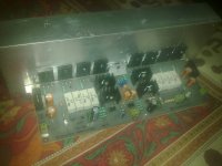
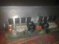
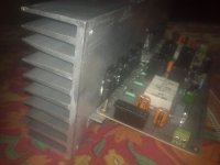
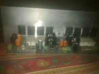
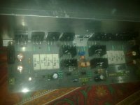
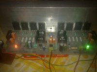
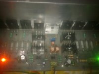
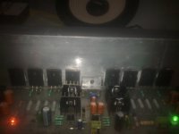
Now, i installed all power transistors and drivers on the main heatsink. Pics attached.
with all 4 pairs of power transistors, there's a problem with biasing. I could not set bias. Earlier i used only 1 pair for testing, i could easily set bias, with the multi-turn trimmer. but it plays music clearly. but there's a problem crept in.
1. i used the same +/-17V supply i used earlier. powered it up, every thing's fine, checked DC offset -2mV and -1.5mV on channel 1 and 2 resp. bias trimmer setting/position intact like i tuned earlier with 1 pair(set at 50mA).
2. now there's 0mV across each emitter resistor, even if turn the bias trimpot, no change, i used a 1k here, but as soon as it is reduced to about 300~330 ohm, bias climbs up instantly showing 110mV across each emitter resistor, and output transistors starts to heat up.
3. I turned it OFF. set bias trimpot at max. again emitter resistors show 0mV across them. played some music, then again bias climbs up at about 60~100mV across emitter resistors. repeated this several times but again same results. as soon as i play some music bias climbs up and transistors start getting hot.
Is the amp oscillating with all 4 pairs installed, i used 47pF miller cap for a start. also there's some difference in voltage across emitter resistors, like one shows 65mV, 2nd shows 58mV other shows 61mV.
also i haven't connected inductor in series with the output.
both channels show same symptoms.
please help !!!
As for 2n5401/5551's, i have replaced them with BC546/556. left them in place. Good.
Now, i installed all power transistors and drivers on the main heatsink. Pics attached.
with all 4 pairs of power transistors, there's a problem with biasing. I could not set bias. Earlier i used only 1 pair for testing, i could easily set bias, with the multi-turn trimmer. but it plays music clearly. but there's a problem crept in.
1. i used the same +/-17V supply i used earlier. powered it up, every thing's fine, checked DC offset -2mV and -1.5mV on channel 1 and 2 resp. bias trimmer setting/position intact like i tuned earlier with 1 pair(set at 50mA).
2. now there's 0mV across each emitter resistor, even if turn the bias trimpot, no change, i used a 1k here, but as soon as it is reduced to about 300~330 ohm, bias climbs up instantly showing 110mV across each emitter resistor, and output transistors starts to heat up.
3. I turned it OFF. set bias trimpot at max. again emitter resistors show 0mV across them. played some music, then again bias climbs up at about 60~100mV across emitter resistors. repeated this several times but again same results. as soon as i play some music bias climbs up and transistors start getting hot.
Is the amp oscillating with all 4 pairs installed, i used 47pF miller cap for a start. also there's some difference in voltage across emitter resistors, like one shows 65mV, 2nd shows 58mV other shows 61mV.
also i haven't connected inductor in series with the output.
both channels show same symptoms.
please help !!!
Attachments
As for 2n5401/5551's, i have replaced them with BC546/556. left them in place. Good.
Now, i installed all power transistors and drivers on the main heatsink. Pics attached.
with all 4 pairs of power transistors, there's a problem with biasing. I could not set bias. Earlier i used only 1 pair for testing, i could easily set bias, with the multi-turn trimmer. but it plays music clearly. but there's a problem crept in.
1. i used the same +/-17V supply i used earlier. powered it up, every thing's fine, checked DC offset -2mV and -1.5mV on channel 1 and 2 resp. bias trimmer setting/position intact like i tuned earlier with 1 pair(set at 50mA).
2. now there's 0mV across each emitter resistor, even if turn the bias trimpot, no change, i used a 1k here, but as soon as it is reduced to about 300~330 ohm, bias climbs up instantly showing 110mV across each emitter resistor, and output transistors starts to heat up.
3. I turned it OFF. set bias trimpot at max. again emitter resistors show 0mV across them. played some music, then again bias climbs up at about 60~100mV across emitter resistors. repeated this several times but again same results. as soon as i play some music bias climbs up and transistors start getting hot.
Is the amp oscillating with all 4 pairs installed, i used 47pF miller cap for a start. also there's some difference in voltage across emitter resistors, like one shows 65mV, 2nd shows 58mV other shows 61mV.
also i haven't connected inductor in series with the output.
both channels show same symptoms.
please help !!!
For a start, repost the final form schematic, I no longer which one is your working models, you've posted a few of them. Without any instruments, please.
In my particular case, since I also use Multism, you could send me the msm file, so I don't have to redraw it. Send it to:
dvv@beograd.com
You have been impatient and ran the basic design by us here in record time, you must understand we don't all come here every day, it takes time for it to sink in. Now you are paying the price.
But, not to worry, we were all like you many, many years ago, all this has happened to all of us at one time or another.
In the meanwhile, replace D3 and D4 by 47/1W resistors and try again.
Also, try removing R13, you don't really need it. Just connect the collector to the ground, assuming the ground for it is "clean ground". If it isn't, use a piece of wire underneath to connect it to "clean ground".
And increase those ridiculous 1 Ohm output transistor base resistors. 1 Ohm does nothing for anybody, your bottom value should be 2.2 Ohms at the evry least, and with that type of fast high Ft transistors, start from 4.7 Ohms and go upwards.
Driver base resistor should be at least 47 Ohms, and probably 82 or 100 Ohms.
Driver base resistor should be at least 47 Ohms, and probably 82 or 100 Ohms.
Aniket I guess you checked the obvious like insulation between outputs and heatsink, and checked that you didn't solder one of the output transistors on the wrong side (left right).
Is your amp designed to run off the low supply of + - 17V, are your current source getting enough ref voltage.
Is your amp designed to run off the low supply of + - 17V, are your current source getting enough ref voltage.
Exact working schematic is attached. simulation file also.
i had increased base resistors to 2.2R earlier before powering up for the first time.
it was working fine with 1 pair of output transistors, but what's the problem when all 4 pairs are placed??? why it's behaving like this.??
All transistors are placed correctly and are insulated properly.
Confused..
Attachments
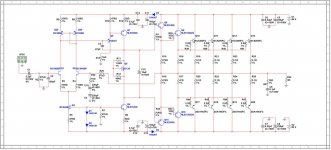
Exact working schematic is attached. simulation file also.
i had increased base resistors to 2.2R earlier before powering up for the first time.
it was working fine with 1 pair of output transistors, but what's the problem when all 4 pairs are placed??? why it's behaving like this.??
All transistors are placed correctly and are insulated properly.
Confused..
Thank you. I'll probably have to redraw it anyway, it seems you have version 12, mine is an older 10.3 and will probably not take it in, but that's all right.
As you line up output transistors, you put their capacitances in parallel. Hence, you need to look hard at the base resistors.
For High Ft transistors (Ft of 15 MHz and upwards), you will need base resistors of AT LEAST 4.7 Ohms, and I have seen as much as 22 Ohms. For example, John Curl used 12 Ohms in his HCA 100W amp. Harman/Kardon uses 10 Ohm resistors in parallel with RF chokes, Marantz uses 22 Ohms in some upmarket models, etc.
2.2 Ohms as you used them would probably be quite enough for older generation power transistors, with a nominal Ft of 4 MHz, such as Motorola/ON Semi MJ and MJL series like 21193/21194, MJ 15xxx, etc.
Also, your emitter resistors are far too low values. They are bias spreader resistors, and a low value of 0.1 Ohms assumes at least about 150 mA bias PER DEVICE, if not more. At 110 mA bias, you will need 0.22 Ohms, at around 90 mA bias, you need 0.33 Ohms, and so forth. It's fairly complex because you need to take into account the ehating up of the output devices, emitter resistor values are defined by calculations - please refer to Bob Cordell's book on this topic, he is very clear about defining overbiased, optimally biased and underbiased
My point is, you can't just stick in a low value and hope for the best. Low emiiter resistor values will produce less THD, but will go wrong elsewhere. In my view, your amp is currently underbiased, and very possibly unable to bias properly. To make amtters worse, you left out a trimmer in your bias circuit, and you now have a practical lesson why that is a bad idea.
Doesn't mean the problem cannot be solved, of course, just means more work than absolutely neccessary.
Try wiring the output transistors with wires to one point . This usually works fine and was common in the past . If you like the amplifier becomes 3 dimensional then .
C3 could be increased in value for interest ( for now , 47 pf goes to 220 pF perhaps ?) .
The VAS transistor might work better on it's own ( without 2N5401 is it , on another page now , hope that's the right sort ) . The input impedance is > 1K5 due to the 22R emitter resistor . A current of 1.5 mA or better should drive that . If that results in DC offset of 20 mV to 50 mV I wouldn't loose any sleep over it .
When working correctly start using a smaller C3 again ( VAS cap ) .
If someone is building an amplifier like this search for a students oscilloscope on eBay . I have one I have in my water logged shed . Somehow it always works and cost peanuts . It is 10 MHz and easy to use . My better one is PC based in the house .
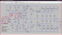
Aniket, in your final circuit a couple of posts back a couple of things stood out. The input filter is ill defined relying on the impedance of the source and also loads the source capacitively. Also R13, the 1K collector load resistor seems an unlikely inclusion.
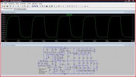
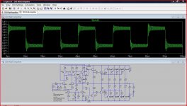
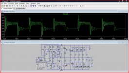
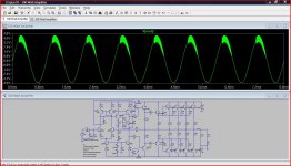
I threw the original circuit into simulation and found it unstable as you can see, even at just 1 watt and 1khz . A couple of "off the cuff" changes resulted in a great improvement. The bias current also altered the "instability" greatly.
The squarewave simulation was at 50Khz.
The final 50 KHz squarewave sim is with the altered circuit.
Attachments
@Aniket
Did some simulating, and here's what I found:
1. Signal generator has no known output impedance - it should have been equal to the output impedance of the preamp, or standard 600 Ohms;
2. C1 would have done better being something like 2.2 ... 10 uF;
3. C2 (220 pF) is hanging on in the air for dear life, so to speak. It has no preceeding reistor to give it any meaningful corner frequency and relies on the source output impedance for that. Assuming a low source output impedanse of say 120 Ohms, the corner frequency would be around 6 MHz, meaning it is quite useless in practical terms. If it had a say 1k resistor preceeding it, and the cap value was say 390 pF, it would have its -3 dB point at around 200 kHz, quite high and low enough;
4. The current generators Q3 qnd Q4 should have been separate by a resistor, value 470...1k. This would ensure smoother operation and less interaction. Also, D1 and D2 should have been bypassed by a say 22...47 uF capacitor, if for no other reason, than just in case;
5. I would have eschewed D3 and D4. Diode pumps, as such circuits are called, and notoriously finnicky and can bleed one to death on occasion. simple say 47...100 Ohm resistors would have been much preferred. Also, cap value of 100 uF is too low, they should have been 330 or 470 uF;
6. R1 and R33, predriver base resistors, are not really necessary if they already exist in the driver and output transistors. Can't hurt, but are an unnecessary complication;
7. As mentioned several times on the forum, MJE 340/350, while being good transistors, are band limting the amp. The following driver transistors have an Ft twice theirs, as do the output transistors. A poor choice;
8. R1(1k), attached to the collector of Q5, is connected to which ground? The power supply ground ("dirty") or the signal ("clean") ground? Why do you need it (just asking)?
9. Why have you not installed a feedback diode across the VAS, in parallel with the Miller capacitor? Does wonders for the sound, but it has to be a fast one (e.g. BAV 20) ...
10. Emmitter resistors (R19-26) are way too low for two key reasons. The first is that they require a LOT of bias current, from 150 mA upwards per transistor. The second is that, according to zour writing, this amp will be used at parties, so it is reasonable to assume it will be driven hard; some addition feedback would be welcome under such circumstances and relatively low load impedance, especially if it should drop lower than nominal (as it surely will, the question is only where and by how much);
11. According to my simulator, you have a solid DC offset under all opearting conditions, it never goes below 150 mV, and, under extreme conditions, climes up to 3V. This is unacceptably high and your speakers will NOT like it, and there are no means of correcting it;
12. Under conditions signal zero, load 4 Ohms, your bias appears to be some 230 mA per transistor. At 56V, that means your power stage is dissipating 103.4 Watts under idle conditions. While good for the sound, this is bad for your power bill and very bad for your heat sinks, which are not likely to hold out for long, and this heating up may explain the rather large offset;
and so forth. The point is - back to the drawing board. Also, Alex may have to redo his artwork to include some components, fortunately small and few in number, there should be space according to the photos.
Before proceeding any further, I would like you to think hard on several issues as per the notes above.
IF you are willing to do that, and obviously if Alex agrees, you have a choice:
A) Use the existing boards with added changes and hope for the best, or
B) Add some completely new circuitry to make it safer to use under duress. This would include building in overcurrent, overvoltage, excess heat and DC circuitry, which would, in all truth, complicate things quite a bit. This also means completely new boards.
To help you realize what I'm putting on the table as choices, I will send you two schematics, one of existing but modified, and another of what I am proposing. Obviously, if you go for what I propose, I would extend any and all help I can, and really, it's all much easier than it looks. And it leaves you with knowledge to use it over and over again, in any other later project.
Lately, I have been experiencing unsurmountable problems with uploading pictures onto the forum, I have yet to discover why. Therefore, I will need to send it to you directly, for which I will need an e'mail address of your choice, just let me know it at my private address dvv@beograd.com.
P.S. That 1 Ohm resistor (R26) in parallel with the 1 uH inductor is also uselessly low in value; replace with 4.7 Ohms/2W.
Last edited:
problem solved
Thanks all,
amp works good with more than a few modifications.
1. increased the value of C3 to 100pF from 47pF.
2. increased the base stopper resistors to 10 ohms and driver base stoppers to 47 ohms. all resistors matched.
3. changed the emitter resistors to 3W type. the 5W resistors installed earlier were different in their values, like 1 showing 0.12 and other showing 0.16. so changed them to 0.1R 3W matched resistors.
4. increased the VAS current to 7mA by reducing R6 to 68 ohms.
5. done with the changes.
i had already installed the bias trimmer before even powering up for the first time. a fixed resistor is only shown in the simulation.
connected the amp to the same +/-17V supply i used earlier, without any load and input connected. checked output, shows -2.5mV. fine. checked voltage across 1st emitter resistor, shows 0V(bias trimmer was turned to max resistance). gradually turned trimmer clockwise to tune bias. at about 60 ohms, voltage across 1st emitter resistor is 7.5mV, that equates to 75mA bias current. fine. checked across all emitter resistors on both sides, each shows 7.5mV across them, except one which shows 7.4mV. fine. done with the bias setting. kept the amp on idle for about 30 mins. Checked bias again, it was constant at 75mA per output transistor. all good.
then, connected a speaker and laptop as audio source. good sound again. kept it running loud for 25 mins or so, checked bias again, constant at 75mA.
again connected to the speaker and laptop and listened to some bass songs. bass is really punchy and tight, good control over cone movement.
carried out the same procedure for the other channel also. both the channels working fine now. DC offset is -2.5mV and -8mV for each of the channels.
I am happy, amp is working great.
soon i would get the power transformer 40-0-40V15A AC. searching for a good airy chassis.
Regards,
Aniket
Thanks all,
amp works good with more than a few modifications.
1. increased the value of C3 to 100pF from 47pF.
2. increased the base stopper resistors to 10 ohms and driver base stoppers to 47 ohms. all resistors matched.
3. changed the emitter resistors to 3W type. the 5W resistors installed earlier were different in their values, like 1 showing 0.12 and other showing 0.16. so changed them to 0.1R 3W matched resistors.
4. increased the VAS current to 7mA by reducing R6 to 68 ohms.
5. done with the changes.
i had already installed the bias trimmer before even powering up for the first time. a fixed resistor is only shown in the simulation.
connected the amp to the same +/-17V supply i used earlier, without any load and input connected. checked output, shows -2.5mV. fine. checked voltage across 1st emitter resistor, shows 0V(bias trimmer was turned to max resistance). gradually turned trimmer clockwise to tune bias. at about 60 ohms, voltage across 1st emitter resistor is 7.5mV, that equates to 75mA bias current. fine. checked across all emitter resistors on both sides, each shows 7.5mV across them, except one which shows 7.4mV. fine. done with the bias setting. kept the amp on idle for about 30 mins. Checked bias again, it was constant at 75mA per output transistor. all good.
then, connected a speaker and laptop as audio source. good sound again. kept it running loud for 25 mins or so, checked bias again, constant at 75mA.
again connected to the speaker and laptop and listened to some bass songs. bass is really punchy and tight, good control over cone movement.
carried out the same procedure for the other channel also. both the channels working fine now. DC offset is -2.5mV and -8mV for each of the channels.
I am happy
, amp is working great.soon i would get the power transformer 40-0-40V15A AC. searching for a good airy chassis.
Regards,
Aniket
Attachments
- Status
- This old topic is closed. If you want to reopen this topic, contact a moderator using the "Report Post" button.
- Home
- Amplifiers
- Solid State
- Simple 100W power amp