
The best thing I got from this was to say the decoupling cap might need a snubber . 1 R 1uF is a pure guess . This takes the simple idea of banking caps to using the cap to do something rather special . Slewing of the caps if you like is no small deal . The internal series inductance is the small residual problem ?
After much thought if using TO3 I would try a bus-bar for the decouplers ( take from the bar centre ? ) . Douglas Self talks of twisting wires to cancel inductance . Maybe this is workable ? Having tried it many times it seems hard to say if it worked . Induced hum via the wiring is another story and it is very real. Some time taken playing with PSU layout can work miracles . If you get hum like this use your ears ( via the speakers , cure is to rotate the transformer ) . Often the least hum is not the nicest . Sometimes it is when slightly louder but nicer sounding ( less rasping and more like nice bass notes ) . The spectrum analyzer will often show what is really happening . The 50 and 100 Hz ( 60 , 120 ) will be higher , the upper harmonics lower . This might be a bought product where the staff building it have no concept of quality . One famous British amp was poor in this respect . I suspect that the transformer supplier was changed at some point and no one asked about alignment . Even when correct it was poor . It was perfect when rotated vertically . Alas the case was too small to do that . The amp had a very sophisticated PSU to the preamp . I suspect it was a cure for a problem it shouldn't have had . I simply re-drilled the chassis . Reinstalled the transformer . Rotated about 10 degrees ( 80 from before ) . I stripped out the complex PSU and fitted something less complex as major upgrades . I did fit chokes to the PSU as I had some . The rest was LM317/337 . I have a hunch it was rather good . The chokes were ferrite cored . As they worked in the already good DC side I doubt they did any harm . On the scope they looked to do good ? They are a No No with some people . If used in a simple unregulated PSU they ring like crazy at radio frequencies . 22 000 uH and 2 for $1 .
I dare say my representation of decoupling is wrong . Hopefully it is a push to the right answer .
Last edited:
@dvv
If Lin topology is getting old,
What is your opinion on Apex AX11 topology, simple current mirror allows for push pull Vas instead of CS loaded Vas.
Enjoy your comment as always
Regards
Sorry I missed this . Have said the same myself . Looks very interesting . Some Hiraga designs feel similar .
Hope we are not hijacking the thread for this diversion ? Usually I am the worst at that . I have a bit more respect for this thread as it is real .
Interesting you should say Lin . Others are unhappy to call circuits as Douglas Self uses HC Lin . Gogny and Sinclair are ( 1967 , 69 ) early examples of the generic Self amplifier . I was shot down in flames when I dared call it Modified Lin as I have seen it called . Specifically Lin returned feedback to what we might call his VAS . To some far too different . Doubt the VAS knew the difference . Thinking about it I should build a Lin circuit . with modern bits who knows . Elliot ( ESP ) has it as El Cheapo approximately.
That PSU Ground is on the PCB and is only 1cm from the output devices.
Is that correct?
Yes, it is. This is a must because the snap-in pins of the caps are either 7.5 or 10 mm apart, depending on which I choose to use. If I use 7.5 mm, then the ground is that far away plus a few mm from the output devices, if it's 10 mm, then that plus a few mm.
As for width of that PSU ground, it also depends on the specific design and power device placement, but the vast mjority of my upper PC board plane is ground. Not many can boast that much.
Now that we are describing the same point on the PCB, I can see where my confusion came about.
I call the PSU the big thing attached to the transformer.
There is a common point in there that is typically Power Zero Volts. That's what I call that common point.
But most here would call it PSU ground.
When you said PSU Ground and I asked how far away I was expecting an answer of 10cm to 20cm because I thought you were referring to the PSU.
However, I call the common point where all the big currents converge in a PCB as the Power Ground.
I try to differentiate between all the "grounds" in an amplifier, but when I read other Members posts I have to try to convert their "general Ground" statement into a specific point in space.
Sorry for the confusion in misunderstanding "your PSU ground".
It has been said earlier that speaker ground might be the reference ground point . Without thinking I have usually made it almost that . Perhaps I could in future ? It sort of seems more logical . Douglas Self's suggestion of the PSU caps taken to the star point rather than the bar between caps as a star point doesn't seem to be the vast difference claimed . One advantage of the series bridged amp is supposedly not involving ground at high current . It also allows cheap components to be used as regards voltage .
If you ever try to improve a pre amp it is current that wins the day . For reasons hard to explain pretending a preamp is a mini power amp always sounds better .
There was some controversy in another thread about sound of ultra high performance LM4562 IC. Some of us do not like the sound of it in spite of the supreme specs. Forum member Bonsai reported that in his preamp, with discrete current booster at the output, they sound excellent, and I replied that this current booster is probably what makes it better sounding. So Nigel, using discrete current booster, or discrete circuit capable of substantial current output (avoiding ICs), should be routine when preamps are concerned. You are absolutely right about that. I think that dvv shares the same opinion about IC based preamps.
My intention is to use a power amp converted to op amp . Or should I say recognizing it as an op amp .
Below is where I got the idea from . The odd choice of transistors was ones to hand at the time . The PCB was material in stock . It is to power a Gyro Deck and have enough left over for a CD transport .
The first part creates a 50 Hz square wave from a crystal . Being 74HC series there is enough current to dive the first filter which also sets output ( nice economy of design and no real penalty ) . The next sages are Chebishev which is fine for an unmodulated frequency . Finally the power amp is also a linear phase filter ( thought it more predictable ) . The end result is of very low distortion ( 0.05% or better ) and super compact . The last filter is a free lunch . It changes it from OK to good . Sorry I have lost the complete circuit . You can work it out easily . With proper biasing it might even make an OK sounding amplifier from the output side . From this amp I discovered that the typcial chip amp has about 0.3 V less biasing than ideal ( is 2.1 V should be 2.4 ) . Like me they use feedback to mask it . I feel chip amps are wrong in this way . I understand why they are wrong . It is to ensure rugged performance . The coloured bits were to show someone details of the design . LTP , input subsonic filtering to avoid beat frequency of mains ( e.g . 50.1 Hz + 50 Hz ) , CCS from common 1N4148 . The choke is because I had some . It helps slightly . The phase shift cap is the type recommended . The drawing is for the owner who is not technical although has a good understanding of the maths . I use 1.7 V bias as at 50 Hz there is no obvious problem . Also it gives indication of working . It is not a good feature , good enough is what I would say . 3 diodes and one resistor is not bad . The Vbe bias so love is not so much better I find . If the VAS is on a fixed voltage 3 diodes and a resistor can be OK . Easy is the other word .

This is it more or less . The exact one is lost . This is a 55 Hz filter . It is OK for 60 Hz if the output is OK ( should be ) . I think we still are in the realms of simple amps . Note , if running 30 watts from this it is like the more extravagant claims of 300 watts from chip amps . The non polar caps are to protect the motor if the amp fails .

Below is where I got the idea from . The odd choice of transistors was ones to hand at the time . The PCB was material in stock . It is to power a Gyro Deck and have enough left over for a CD transport .
The first part creates a 50 Hz square wave from a crystal . Being 74HC series there is enough current to dive the first filter which also sets output ( nice economy of design and no real penalty ) . The next sages are Chebishev which is fine for an unmodulated frequency . Finally the power amp is also a linear phase filter ( thought it more predictable ) . The end result is of very low distortion ( 0.05% or better ) and super compact . The last filter is a free lunch . It changes it from OK to good . Sorry I have lost the complete circuit . You can work it out easily . With proper biasing it might even make an OK sounding amplifier from the output side . From this amp I discovered that the typcial chip amp has about 0.3 V less biasing than ideal ( is 2.1 V should be 2.4 ) . Like me they use feedback to mask it . I feel chip amps are wrong in this way . I understand why they are wrong . It is to ensure rugged performance . The coloured bits were to show someone details of the design . LTP , input subsonic filtering to avoid beat frequency of mains ( e.g . 50.1 Hz + 50 Hz ) , CCS from common 1N4148 . The choke is because I had some . It helps slightly . The phase shift cap is the type recommended . The drawing is for the owner who is not technical although has a good understanding of the maths . I use 1.7 V bias as at 50 Hz there is no obvious problem . Also it gives indication of working . It is not a good feature , good enough is what I would say . 3 diodes and one resistor is not bad . The Vbe bias so love is not so much better I find . If the VAS is on a fixed voltage 3 diodes and a resistor can be OK . Easy is the other word .
This is it more or less . The exact one is lost . This is a 55 Hz filter . It is OK for 60 Hz if the output is OK ( should be ) . I think we still are in the realms of simple amps . Note , if running 30 watts from this it is like the more extravagant claims of 300 watts from chip amps . The non polar caps are to protect the motor if the amp fails .
Last edited:
Now that we are describing the same point on the PCB, I can see where my confusion came about.
I call the PSU the big thing attached to the transformer.
There is a common point in there that is typically Power Zero Volts. That's what I call that common point.
But most here would call it PSU ground.
When you said PSU Ground and I asked how far away I was expecting an answer of 10cm to 20cm because I thought you were referring to the PSU.
However, I call the common point where all the big currents converge in a PCB as the Power Ground.
I try to differentiate between all the "grounds" in an amplifier, but when I read other Members posts I have to try to convert their "general Ground" statement into a specific point in space.
Sorry for the confusion in misunderstanding "your PSU ground".
Not at all, Andrew, just a small adjustment of our semantics and we're back on track.
There was some controversy in another thread about sound of ultra high performance LM4562 IC. Some of us do not like the sound of it in spite of the supreme specs. Forum member Bonsai reported that in his preamp, with discrete current booster at the output, they sound excellent, and I replied that this current booster is probably what makes it better sounding. So Nigel, using discrete current booster, or discrete circuit capable of substantial current output (avoiding ICs), should be routine when preamps are concerned. You are absolutely right about that. I think that dvv shares the same opinion about IC based preamps.
Indeed I do. In audio, by far the best thing you can do is to add a small discrete current booster. This offloads the op amp, as it then acts as an almost pure voltage amp, and that they do rather well.
The thing is, this seems to work just as well on regular op amps as well as on those specifically advertised for good current boosting, such as working into 600 and 50 Ohm loads, as headphones amps, etc.
Better yet, try it out and be prepared to be pleasantly surprised at the sound quality so easily available from even common, garden variety op amps, such as, say, LF356, LF357 and especially OPA 37.
I think the thing to remember is op amps have excellent performance when no load . Boosters do more good than harm .
As I think I said before a NAD 3020 is very OK as a workhorse . It also keeps you honest . If you can not beat it as a preamp start again . Doubtless it is a bit agricultural and has hum/hiss . I have become so fed up with borrowing one that I have asked that friend to find me one . Being very mean it is a $50 budget . Power amp is OK . 2 x NAD 3020 is almost hi end . One as pre one as power amp . He has a few ( !?! ) so borrowing one isn't a problem . He gave me a Naim CDi recently ( needs a DAC inside , me thinks it is time to have worlds best Naim CDi with non standard DAC ) . He seems unwilling to give up a NAD !
As I think I said before a NAD 3020 is very OK as a workhorse . It also keeps you honest . If you can not beat it as a preamp start again . Doubtless it is a bit agricultural and has hum/hiss . I have become so fed up with borrowing one that I have asked that friend to find me one . Being very mean it is a $50 budget . Power amp is OK . 2 x NAD 3020 is almost hi end . One as pre one as power amp . He has a few ( !?! ) so borrowing one isn't a problem . He gave me a Naim CDi recently ( needs a DAC inside , me thinks it is time to have worlds best Naim CDi with non standard DAC ) . He seems unwilling to give up a NAD !
My first PCB
Inspired from Alex MM, i designed a PCB for my amp. The circuit is a bit modified with feedback current sources for LTP and VAS. this is my first attempt to design a PCB . Parts numbering needs to be done. I made only the layout first.
Inspired from Alex MM, i designed a PCB for my amp. The circuit is a bit modified with feedback current sources for LTP and VAS. this is my first attempt to design a PCB
. Parts numbering needs to be done. I made only the layout first.Attachments
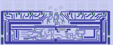
Inspired from Alex MM, i designed a PCB for my amp. The circuit is a bit modified with feedback current sources for LTP and VAS. this is my first attempt to design a PCB
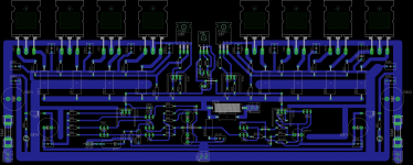
I am not an expert but I doubt those ground rails has run too complex,why not use more refined star.
I hate to hear that tiny bit of krrrrrrrrr sound in speakers when input is grounded .
Last edited:
I am not an expert but I doubt those ground rails has run too complex,why not use more refined star.
I hate to hear that tiny bit of krrrrrrrrr sound in speakers when input is grounded .
Hi Jayadev,
it's just a attempt for learning. i have designed a new PCB in Sprint Layout with dedicated star ground.
Currently, i am using PCB's designed by AlexMM, and they are great. amp is dead quite, no hum hiss or krrrrrrr, even without enclosure or chassis.
Star is like the perfect partner in life . It is more of a concept than reality . The thing I will have to use soon is a Ground-plane . I think to make the top PCB layer copper ground is OK . That is to do the opposite of Star . That is it makes the resistance so low that the nasty layout does no harm ( oh that it was so simple ) . The Bus Bar works well and is easier to be certain it is working . Just swap things around for low noise is not a bad way to do it . Be careful , hum which is low in harmonics and slightly higher in amplitude might sound nicer . Rotates transformers to do that also . If it goes from - 86 to - 82 db 50 ( 60 ) Hz and sounds nicer at - 82 dB it might be that the 150 Hz is lower ? You might find it was 150 Hz - 86 db and then - 92 dB . What you might find it is a warmer sound with better openness . Truth is we hate 150 ( 180 Hz ) ? Largely speaking 50/100 ( 60 / 120 ) is what we hope for . 50 Hz hum is OK , 60 Hz is more intrusive !!! I plan to use 40 Hz one day . It is the limit of what transformers do well ( up rate by 50 % at a guess ) .
Anyone know of a good Sound-card and program for Spectrum analyzer . - 90 dB readings ?
Anyone know of a good Sound-card and program for Spectrum analyzer . - 90 dB readings ?
I've been using a ground plane like forever, for at least the last 15 years or longer. People shy away from it because it requires a double sided PCB, with the whole through hole jazz packed in one deal, but they forget that:
1. It gives the ground an exceptionally low impedance, not possible in any other way,
2. It improves the S/N ratio typically by about 3 dB (although this varies), which is not to be scoffed, even if not quite a revolution,
3. Reduces problems with stray capacitances al least to a part, also succeptibility to RF interfearance and
4. Allows for more dense parts packaging, and in a competenet design (e.g. by Alex), it completely does away with any wire connections on the PCB.
So Nige, definitely, by all means, do go for the ground plane.
Do you do what I would do . That is simply connect where needed and forget the usual rules ? Or do you layout in a certain way ? I suspect do it as if a standard design then add as much cooper as possible the best ? Easy PC and similar Gerber PCB design tools have automatic copper in fill . It is called minimum etch and can save money also .
Alex MM,
could i have the layout files of the PCB you designed for my amp.
Regards,
Aniket
Before asking anyone for this, Aniket, you should consult with whoever is making your PC boards regarding the exact format he/she needs to make them.
I speak from very recent experience with Alex - he sent me the files, but it turned out that the man making mine needed them in a somewhat different format. This put Alex in a situation to have to redo it twice over until we got it right. These are typical teething problems, once you do get it right there should no longer be ynaproblems later on, but making sure would help Alex not to have to jump through too many hoops.
Just my 2 cents' worth.
- Status
- This old topic is closed. If you want to reopen this topic, contact a moderator using the "Report Post" button.
- Home
- Amplifiers
- Solid State
- Simple 100W power amp