And you say Dvv you had no part in it . Shame on you .
Aniket what you don't know is Dvv and I have opposing philosophies . He likes amplifiers like yours with the most amassing complexity of details . He says of me I take parts out until it stops working which is 101 % true . Funny thing is we like the same stuff ! That would be for example that power supplies are important . One can never have one that is too good . My suspicion is your amp is good enough to see the PSU as it's weakness . Cost is the problem not your design .
Dvv . If Aniket is interested would you advocate a small PSU where the 1N4007's are ? Take them out is all that is required . It could even have a low voltage switch if friends use the amp . On that note lowering the input side voltage can have dramatic consequences . Nicer sound is one .
It was you Brits who taught me that the devil is in the details.
 That revenge is a dish best served cold. That birds of feather flock together. And so forth. And that's not even mentionng Jack and Jill.
 To be honest, you Brits also taught me the essence of tradion and several oustanding examples of applied democracy. And of course, all about cider, in case of which Brittania still rules the seas and the skies. Best jams and biscuits still come from Britain (my apoligies to all others). And of course, Lotus and Cosworth are still based in Britain, are they not?
In my view, Britain is the only organized anarchy in the world. So why are you surprised, Nige, when I turn out to be a faithful stident?
Essentially, the only true difference betwen you and me is that you are trying to prove an amp can do without this or that, while I acknowledge they actually work better with this or that. But compare our philosophies and I think you'll agree they corresponmd to each other very well, we mostly differ in our way on the road to the realization.
As for Aniket, I'm simply trying to help, nothing else, it's definitely HIS project, period. I only wish he wasn't in such a breakneck hurry to get it going, I have a feeling it could have been better yet. I could have passed on to him the essence of the German LAS amp, some details in it are still unsurpassed, 40 years dwon the road, but before I had a chance to even mention it, he had made the boards.
Thanks dvv and Nigel for all your help and teachings. I would like to say that, it is just a beginning, this amp is a start, many more projects would definitely come in future that we shall design and construct with patience and intelligence.As for Aniket, I'm simply trying to help, nothing else, it's definitely HIS project, period. I only wish he wasn't in such a breakneck hurry to get it going, I have a feeling it could have been better yet. I could have passed on to him the essence of the German LAS amp, some details in it are still unsurpassed, 40 years dwon the road, but before I had a chance to even mention it, he had made the boards.
My cousin want's me to make an amp that would feed his 2 ohm 400W car woofer in his house and .....A friend of mine who is an occasional DJ and party organizer, wants me make pro amps for him,
i asked him about his setup requirements, his parties would mostly be indoor, sometimes outdoor. I denied him and excused that i need some time to make an amplifier to suit his requirements.
In the meantime, I advised him to buy good pro audio equipment and he ended up buying 4 JBL SRX722, 2 JBL SRX 725 and 2 JBL SRX728 subs. and 4 StudiomasterProfessional PA6 amplifiers
STUDIOMASTER PROFESSIONAL
he is not satisfied with the sound quality of his setup, he says, bass is good but mids and highs aren't. so he wants me,, to make a HIFI pro amp for him.
So, this pro amp is in the waiting list and would not be more than 600W@4 ohms. pro amps are way too complex for me now, and i need to gain experience and knowledge to make amps of this power range. and it's not only about power, more importantly, its about how safely and reliably this power is delivered, we all know that.
I am learning and would gain some experience with my current project which is too a high power amp. also I have all of you here with me to support. Thanks again.
Regards,
Aniket
Last edited:
@Aniket
I agree you need more experience- no matter how much of it you have, you can never have too much of it.
Pro class amps are in many ways similar to home amps, but are different in some aspects. Their No.1 requirement is reliability even under deadly conditions. You need to know your protection circuits in and out and have them sorted out very well. Don't even think of using idiot fuses for "protection".
You need to learn by personal experience which transistor goes best with another; while most will work together, not all the resulty will sound the same even if they measure the same.
But most of all, you need to free your mind from the HD obsession. THD performance and sound quality have very little to do with each other; amps with zero NFB have much worse specs than high global NFB amps, yet they generally sound better to much better. On the other hand, some measurements can tell you a hell of a lot if you know what to expect. It simply takes time for one to try it out and see for himself.
So, all in good time.
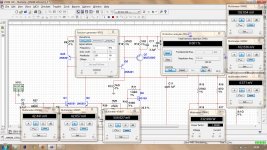
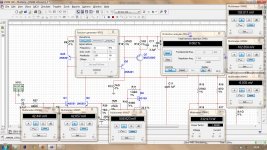
Till the time i could get the required power transformer and chassis, i did some tweaking in the simulation and made some changes in the circuit,
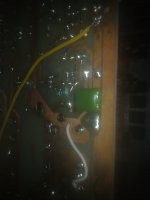
included R34 560R and C16 0.1uF and soldered them on the copper side of PCB, changed C11 to 0.1uF and R36,37 to 100 ohms. Increased predriver current by reducing R15,18 to 270 ohms.
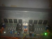
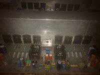
powered the amp with +/-28V supply, set bias at 75mA per transistor, checked DC offset, 1.8mV and 8mV DC on channel 1 and 2 respectively. amp was stable no signs of oscillation.
Also changed the miller cap C3 to 68pF. tested it with a number of values starting from 100pF which was installed earlier when the amp was oscillating originally with 47pF.
tried 100, 82, 68, 56, 47, 39 and 33pF in C3 position.
amp was stable with 56pF as least possible value of C3, with 33,39 and 47pF showing oscillation. So i installed 68pF as a fail safe value for C3 and would gain some high frequency performance.
with all the changes mentioned above there was a prominent difference in sound. Mids were smoother and soft and highs, very crisp and sharp. and the bass was even tighter, faster, more deep. bass is really awesome.
Regards,
Aniket
included R34 560R and C16 0.1uF and soldered them on the copper side of PCB, changed C11 to 0.1uF and R36,37 to 100 ohms. Increased predriver current by reducing R15,18 to 270 ohms.
powered the amp with +/-28V supply, set bias at 75mA per transistor, checked DC offset, 1.8mV and 8mV DC on channel 1 and 2 respectively. amp was stable no signs of oscillation.
Also changed the miller cap C3 to 68pF. tested it with a number of values starting from 100pF which was installed earlier when the amp was oscillating originally with 47pF.
tried 100, 82, 68, 56, 47, 39 and 33pF in C3 position.
amp was stable with 56pF as least possible value of C3, with 33,39 and 47pF showing oscillation. So i installed 68pF as a fail safe value for C3 and would gain some high frequency performance.
with all the changes mentioned above there was a prominent difference in sound. Mids were smoother and soft and highs, very crisp and sharp. and the bass was even tighter, faster, more deep. bass is really awesome.
Regards,
Aniket
Attachments
That is truly fascinating . I had a friend who listen to Indian Opera . It would need good high frequency ability . Even if you don't it is a pointer to taste . Excellent progress .
The India Opera I listened to was with a trained voice and gifted amateur . I could tell . Not all Indian people liked him . He taught me for years . He was gifted hi fi designer . His son lives in your city .
Nirad C. Chaudhuri - Wikipedia, the free encyclopedia
The India Opera I listened to was with a trained voice and gifted amateur . I could tell . Not all Indian people liked him . He taught me for years . He was gifted hi fi designer . His son lives in your city .
Nirad C. Chaudhuri - Wikipedia, the free encyclopedia
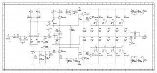
One thing . Can you simulate adding capacitors to R6.14 . They should come in at 5 kHz is my guess ( -3dB ) . It might change dominant pole requirements . The beauty is it keeps the stage match as now except at high frequencies . It might be a fight between loop gain and easy of drive . I have no idea how it would work . I have a hunch it is a free lunch . The hunch says lower 10 kHz distortion . I am feeling too lazy to do the maths . That's the first time in my life I ever said that .
R14 looks likely to be the one to try . R6 is worth asking the simulator to check out . I doubt it will be the one that makes a difference . Tell me if I am wrong as I would be surprised .
10 R Xc = 1/2PifC . -3 dB is where Xc = R therefore C = 1/2PifR . C = 1/2 x 3.14 x5000x10 = 3.3 uF to a good approximation . My best guess is 5 kHz is the critical frequency . Hopefully C3 stays the same . Even if it had to go to 100 pF you might win more than you loose . The idea is to have increasing loop gain when you need it most . I think on simulation it should show something ? My theory is the 10 R resistor usefully helps the previous stage to drive it . Some would say you don't need that resistor especially when a Darlington . Probably true . 3.3 uF will keep DC conditions the same . I would use a 100 V polyester cap . Theory is they sound better than 63V type . 16 V high grade electrolytic like Panasonic FC would be OK . There will be a phase shift . It might come up on simulation as unworkable . Poor old me always does it the hard way . I must learn simulation . Anyone near Oxford willing ? I am told this program you use is great .
D3/4 is an excellent place to introduce a quiet PSU in the future if you choose . Just remove them . You can try both increased and reduced voltage . Both can be good . The former to have nicer clipping , the later for power . +/- 10 V of output voltage if transistors OK is an idea . I would use 100 VA and 4700 uF unregulated , should be fine .
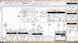
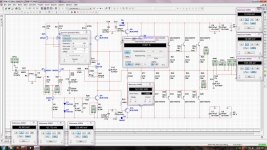
Attached are the simulation results with the addition of 3.3uF cap in parallel with R14. THD figures are 0.001, 0.001, 0.002 and 0.002% for 1,5,10 and 20kHz @ 330 watts into 4 ohms respectively and these were identical without C17 3.3uF cap. C3 is same as 68pF.
Regards,
Aniket
Regards,
Aniket
Attachments

Attached are the simulation results with the addition of 3.3uF cap in parallel with R14. THD figures are 0.001, 0.001, 0.002 and 0.002% for 1,5,10 and 20kHz @ 330 watts into 4 ohms respectively and these were identical without C17 3.3uF cap. C3 is same as 68pF.
Regards,
Aniket
I could say try 0R ?
Try at 0.5 W 50 kHz if it will let you .
Maybe just try it for real ? No harm I guess ?
Very interesting . We might be beyond the simulators ability ? In theory something should happen . Especially at low wattage .
:
You really are an excellent designer of PCBs, your designs are spectacular. thanks for uploading the PCB, as I seem to be seeing it running on that version 1.
PS: I would like to learn to design as you do.
Hi,
...you have, attached below, all files ,you need ,to made this nice amplifier .
Was my pleasure to help again.....
Alex.
You really are an excellent designer of PCBs, your designs are spectacular. thanks for uploading the PCB, as I seem to be seeing it running on that version 1.
PS: I would like to learn to design as you do.
Hi Aniket can you post a gain bandwidth plot till 1MHz. Ac SIM.
Hi, Vostro, could you please guide me, how to simulate that in multisim??
I could say try 0R ?
Try at 0.5 W 50 kHz if it will let you .
Maybe just try it for real ? No harm I guess ?
Very interesting . We might be beyond the simulators ability ? In theory something should happen . Especially at low wattage .
HI Nigel,
0R for R14.. ???
0.5W @ 50kHz, would simulate that.
That's interesting . I always work with a spectrum analyzer on a real amplifier . I had forgotten you get THD figures . Sometimes I work out THD for my amps . When the spectrum is full of nasty 5 th 7 th and 9 th harmonics the THD hardly changes . One usually says if the nasty ones are below - 90dB it is OK .
I would suggest you try R14 as 10 R and use 3u3 . You might on voices typical to Indian music sense a slight reality that you don't have now , an open mouth quality which is more incisive . It would be to western ears a bit shrill . My favourite Quad 303 has this . It's distortion spectrum looks like a suspension bridge .
Dr Chaudhuri had an Arcam amp and Royd speakers . His Arcam went wrong . We replaced the TLO71 op amp in the middle section of the amp with NE 5534 and a 10 pF polyester a per Aracm recommendation . The amp would have measured about the same . It didn't sound the same . He was delighted . This is when we listen together from then . At 97 years of age I would guess he had been to the garden shop to get sand to damp the speakers and weigh them down . I was angry because I would have done it . He used his shopping trolly . It was 1 miles to the shop , 4 trips . He had weights and broom sticks to anchor the speakers against the walls . That worked . He covered his speakers in layers of carpet . It worked as it kept reflected energy down . As he said . To damp inside a speaker is perhaps a mistake , do less of it . Not to damp outside is also a mistake . My speakers don't have boxes so less of a problem . Also they have no conventional damping .
One very good thing from this is Dvv and I have been saying for some time a R 14 in everybody's amp might do more good than harm . Strict followers of the " Blameless " design say not . When a Darlington it is complicated . I suspect if you made your amp a single transistor and retained R14 it would work . It might even sound better . It rides on a knife edge so I am not sure . I often arrive at 16R when I use a single transistor .
If you loved the suspension bridge distortion and wanted more there is a way . The LTP input current mirror could be replaced with resistors . This will reduce slew rate and might cause distortion . Slightly reducing input bandwidth would stop that . If the resistors were made unequal eventually the THD would rise . If you let it double it should be mostly second harmonic that is added . You would arrive where Naim audio did in about 1980 . 12K and 1 K if I remember ? My belief is it's true designer was used to using Quad 303 and wanted the same . Usually a single input transistor is the only route . That makes the amp difficult to set up ( JLH says how ) . Naim didn't exactly get the same as the 303 , they got close .
Nige, there is nothing to learn in simulation, except where's what. Other than that, use it as you would the real parts, only in electronic form.
I didn't get on with LT Spice nor Simatrix ( ? ) . Too bloody lazy to learn mostly . I sort of asked my friend John to teach me . He is so used to designing chips etc . I am not asking him to teach me to be a better swimmer , I am asking him to teach me to swim ! It was getting embarrassing so I stopped asking . That is the problem with genius friends , they assume we are one step away from being them . As said lazy comes into it .
Not ruin . Make optimum ? I am absolutely certain good slew rate amps sound good . It is nothing to do with fast . It is to do with plenty of current to push into the bass of the VAS . When a Darlington VAS the current required is less . The bad sound of a low slew rate amp I suspect is good old stage matching as is in voltage amps . If you ever try to improve a pre amp it is current that wins the day . For reasons hard to explain pretending a preamp is a mini power amp always sounds better . Regardless of how others see it a VAS might be the same . When I build my next pre amp it will have 8 watts 8 R output . Then I can use it as a amplifier also . Absolutely no reason not to . My TV has to feed the system that way as it avoids a hum loop . As the TV headphone amp is lightly loaded it acts as a nice op amp .
- Status
- This old topic is closed. If you want to reopen this topic, contact a moderator using the "Report Post" button.
- Home
- Amplifiers
- Solid State
- Simple 100W power amp