Hi Dvv and Aniket . I was in Tunisia last week, I resisted the hotel internet and had a true holiday . We touched 43 C briefly ( and in Libya ) . 28 C mostly .
Dvv you put it well . The money stacks up quickly if metal or fans . My idea is sometimes we need a full 1000 VA 24/7 . If the load is predictable we have two problems . Heat and money . Ridiculous when we are talking the power of a 50 kph moped ( 1.34 HP ) .
Water has the greatest heat capacity of any substance as long as the temperature range is OK . It also has very poor conductance . Water heated at a top of a test tube will boil whilst ice at the bottom remains ice . Pumping water is the answer in both extracting and getting rid of heat . Car heater radiators are cheap and have blowers built in .
It has always bugged me how difficult this problem is . 1000 VA seems a trivial power output . It isn't . No wonder class D is well liked ( not by me ) .
I have been accused of being a heat freak several times in life, and it's probably true, at least to a point. It's a fact I am obsessed with cooling, but that's only because I have learnt that this is a much bigger problem than is usually assumed.
I am appaled by designers letting their amps heat up to over 60 deg. C in a jiffy. To me, that is wrong, to me that means they underestimated the amp's capacity and need to dissipate more to much more power than the simpleton math show. Far too many designers think of speakers as straight, ideal resistances and impedances, when in fact they are anything but. Hence, to reach the power levels sometimes desired, amps have to produce not rarely twice the nominal power, and that's only assuming a phase shift of -60 degrees.
In the real world, such large phase shifts are also accompanied by impedance drops; say your nominal ipedance drops down from 8 to 4 Ohms, AND has a -60 degree phase shift thereabouts, the amp sees an equivalent of 2 Ohms where it's 8 nominally. Consequnetly, it has to deliver 4 times as much current. This produces a hell of a lot of heat.
Also, heat sinks are both expensive and take up a lot of inside the case real estate, and the customer can't see them, so cmpanies tend to skimp on them.
The easiest solution is forced air cooling. This can be very effective if done right, but will always have the drawback of producing fan whooshing sound.
One of the best overall solution to this I saw in an old reVox 720 power amp. There, the power devices (TO-3 metal cans) were installed on finned heat sinksas normal, but the sinks were shortened by about 5 cm and underneath a fan was mounted, pushing air upwards across the sinks and out of the case through top cover perforation cutouts. The fan came on when the heat sinks reached about 60 deg. C and worked progressively, not just off/on.
I have never seen water cooled power amp heat sinks, though I know they exist. I imagine that would be some messy work, as one would need a small water tank and a small pump to move that water along, plus coupling hoses/pipes of some kind. I also imagine even that small water pump would make some noise, which is a no-no for me. So I cannot know or comment on efficiency. I know that the Italian heat sink manufacturer Pada sells them on "as is" or custom basis ( PADA dissipatori per Elettronica, DISSIPATORE di calore ) on their "Superpower" series, complete with thermal analysis.
Me, I just like overdoing it. The math for my amp says I need a heatsink with a 0.9 cooling coefficient, so I'll use those with an 0.6 coefficient.
I have never tried water cooling a power amp. However, there are some very nice, self-contained units that are designed for PCs which I have used successfully. I could imagine - with a large enough case - that one of these units could be re-purposed/retrofitted and used with an amp heatsink. It would definitely be a custom solution, but I believe doable for someone willing to tackle the project. ")
A PC CPU cooler for a power amp? I don't think so, Nige, I think their effciency just isn't up to it.
Also, you would need to do some maths, what's more cost efficient, a smaller heat sink with say two such CPU coolers, or simply a larger heat sink doing it all on its own?
That may a be a solution in case you are highly constrained by space considerations, meaning simply no space for large heat sinks, yet considerable power (for the space) still required.
I don't know, I could be wrong, but I just don't see it as true solution.
A water cooling system coupled into the domestic "under floor" heating system would be very workable.
The water temps in the flow side of UF heating are quite low. The return temp is even lower.
Dry break couplings would allow connecting any number of ClassA amplifiers into the heating/cooling system.
All the potentially noisy mechanicals are located elsewhere in the house.
The water temps in the flow side of UF heating are quite low. The return temp is even lower.
Dry break couplings would allow connecting any number of ClassA amplifiers into the heating/cooling system.
All the potentially noisy mechanicals are located elsewhere in the house.
I know the water cooling route is difficult . The PC devices a bit different to our needs . I hoped someone might come forward as I have a real interest in this .
One idea I had was cooking oil . All NPN deices in one bath and all PNP in an other . Circulate the oil through the same car heater matrix . Specific heat capacity is about 1/3 that of water . Maybe on the swings and roundabouts better than water ? The idea is nothing fancy required in the engineering . TO247 on flying wires like fish frying in the oil . Keep oil down to 60 C if possible . I suspect there is no need for oil if the resistance of the water can be kept high . Maybe a standard water filter and ohm meter to say how good ?
One idea I had was cooking oil . All NPN deices in one bath and all PNP in an other . Circulate the oil through the same car heater matrix . Specific heat capacity is about 1/3 that of water . Maybe on the swings and roundabouts better than water ? The idea is nothing fancy required in the engineering . TO247 on flying wires like fish frying in the oil . Keep oil down to 60 C if possible . I suspect there is no need for oil if the resistance of the water can be kept high . Maybe a standard water filter and ohm meter to say how good ?
If using warm water then beware Legionella !!!!!!!!!!!!!
50/50 Mix with antifreeze will solve that
A water cooling system coupled into the domestic "under floor" heating system would be very workable.
The water temps in the flow side of UF heating are quite low. The return temp is even lower.
Dry break couplings would allow connecting any number of ClassA amplifiers into the heating/cooling system.
All the potentially noisy mechanicals are located elsewhere in the house.
I was thinking of a generator using gas . New cars with hybrid electrical systems should have 230 V bi phase built in . Great to have if the power fails and gas is still flowing . Might even be cheaper ? Fiat had this years ago called Totem . It was I think to serve about 6 houses ? It should have a water heat exchanger also to couple up to the heating . This would also preheat the car in winter from the heating system . The gearbox disabled until umbilical's disconnected . Naturally charging of the batteries if required from the house electricity . These cars could back up the grid if a power station is out . The electricity can be reimbursed if the correct type of meter is fitted . This could be life or death in in some regions . As the weather gets worse we might be glad to have hybrid cars . Not to have this would be like a tractor without a power take off . The UK will soon have too few power stations . This could fill the gap . Heaven forbid we need it and what bad planning etc .
I like your idea of plumbing in the hi fi .
The are now heat pumps that can be fitted into 2 x 2 metre courtyards . I think I saw they go down 30 metres ? Spare heat is put there in the summer .
Anti freeze degrades the heat capacity of water . I imagine 15 % would be OK .
This basic amplifier would convert to class A so all of this is mildly relevant .
I would have been so proud to have designed it . I have said for years amps can be this simple and work . How many if they knew it have been put to shame here ?
It reminds me of the car Dodge Viper .
Doubtless in the serious PA world it will fail . Slightly too heavy and needs more cooling . For everyday use it is great .
I don't think you will ever get the hear some big Klipsch speakers . That would be a test for you amp . For some that is 105 db for 1 watt yet able to take 300 . Then an amp gets tested . It's 1 watt matters and it's hum .
La Scala II Floorstanding Speaker | Klipsch ®
Dvv you should take some credit I feel ?
Huh? Whatever for? What have I contributed to the present state of the design?
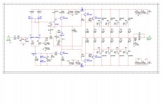
Curretly, I am rather concerned with the emitter resistors, which are far too low a value for what I suspect the bias current is. Which means the amp is grossly underbiased if Aniket's to keep the ultra low value of 0.1 Ohm, and will possibly become very harsh once it gets seriously hot, even possibly unstable.
My feeling is that he should be using something in the range 0,22 ... 0,33 Ohms. For 0.33 Ohms, the bias could be 65-85 mA per transistor, for o,22 Ohms it woild have to be 115-130 mA per trannies, off hand. Remember Nige, you and I had this discussion a while ago for exactly the same reasons, you also used too low emitter values.
Last edited:
Hi dvv and nigel,
bias current is 78mA per transistor, got 7.8mV across each transistor.
simulation shows 78mA as optimum bias current, THD20 is minimum at this current and increases again with increase in bias. THD1 increases to 0.001% and THD20 to 0.005% with 100mA bias. maybe the TEF configuration allows lower bias for lower THD figures.
regarding the emitter resistors i have already ordered some 0.22R 5W resistors from a local shop. 0.33R are not in his stock, but he has 0.5R.
Regards,
Aniket
Hi dvv and nigel,
bias current is 78mA per transistor, got 7.8mV across each transistor.
simulation shows 78mA as optimum bias current, THD20 is minimum at this current and increases again with increase in bias. THD1 increases to 0.001% and THD20 to 0.005% with 100mA bias. maybe the TEF configuration allows lower bias for lower THD figures.
regarding the emitter resistors i have already ordered some 0.22R 5W resistors from a local shop. 0.33R are not in his stock, but he has 0.5R.
Regards,
Aniket
Off hand (no calc), at 78 mA per trannie, you should be using 0.33 Ohms, or possibly 0.27 Ohms.
These should give a nice, even bias spread across the board, which would linearize your output stage just that little bit better.
Anyway, the point is that you did do something about it. A word of caution - do not expect anything spectacular to happen, no revelation, no heavenly light shining on you. At best, you might notice a slightly better defined treble range. But at higher powers, your amp will definitely be better served.
And you say Dvv you had no part in it . Shame on you .
Aniket what you don't know is Dvv and I have opposing philosophies . He likes amplifiers like yours with the most amassing complexity of details . He says of me I take parts out until it stops working which is 101 % true . Funny thing is we like the same stuff ! That would be for example that power supplies are important . One can never have one that is too good . My suspicion is your amp is good enough to see the PSU as it's weakness . Cost is the problem not your design .
Dvv . If Aniket is interested would you advocate a small PSU where the 1N4007's are ? Take them out is all that is required . It could even have a low voltage switch if friends use the amp . On that note lowering the input side voltage can have dramatic consequences . Nicer sound is one .
- Status
- This old topic is closed. If you want to reopen this topic, contact a moderator using the "Report Post" button.
- Home
- Amplifiers
- Solid State
- Simple 100W power amp