Hello dvv!
*Mr. dvv if you are able to give everything you have said about my schematic audio amplifiers send the Serbian language to my e-mail address!
thank you!
Ziveli!!
Живео и Ти мени!
No, unfortunately, I do not. I got tired of futile arguments with the locals and gave up writing altogether. Or delegated it to a case-by-case only.
What wouild you like to know?
The 741 does use a Widlar current mirror in its biasing circuitry, but it was not designed by Bob Widlar. It was designed at Fairchild Semiconductor by Dave Fullagar, who co-founded Maxim. The 741 began its phenominally successful life in 1967 as a successor to the Widlar-designed uA709.
One needs an inductor in parallel with a resistor at the output only if one's power supply is lacking, and one has inherent design instability issues.
My first job is to make sure I do NOT need them. Anyway, that's a Boucherot circuit, and as most things French, it is perversely unnecessary.
The inductor in parallel with resistor is to help measurements . It damps ringing . If it needs the resistor or not is a ears thing . I wonder if a smaller inductor is better ? The overshoot on square-waves so often called marginal instability was nothing of the sort . The proof is the resistor cured it . Common sense says at best it would do nothing .
No 22 I love the use of a bootstrap current source on your VAS . If it was a conventional current source like on your input pair the amp might be slightly quieter . You could use the same voltage reference for both current sources meaning a transistor and resistor is all that is required . It could even fit in the same holes . I champion bootstraps , however the transistor CCS is helpful .
I believe the 1963 date corresponds to the design of the ua702, a Widlar design and the first integrated op-amp of which I am aware. A couple of years later Widlar improved upon the 702, which he never particularly liked, with the design of the ua709. The 709 had its own problems with latch-up, difficulty of compensation, and other things. Fullagar's ua741 (now most commonly LM741) improved on the 709 and became - afaik - the world's first internally compensated op-amp.
Always interesting:
Bob Widlar - Wikipedia, the free encyclopedia
Best,
Anson Whealler
Always interesting:
Bob Widlar - Wikipedia, the free encyclopedia
Best,
Anson Whealler
Anson .
I always say to my friends like with Jesus we weren't there . Interesting to think Bob might have designed it in 1963 .
Jim Thompson's name comes to mind . I think MC 1530 is still made . It is rather good if the 12 V range is OK . The design is a great starting point .
HC Lin . There is often confusion about latter Lin circuit as used by Douglas Self and Naim Audio to say just 2 . Lin said when his work on op amps was declassified op amps became common . The military paid for them and found them useless in a military application . I suspect Lin was the originator of op amp style amplifiers ? He said his friends thought he had been demoted when working on op amps . I seem to remember it was an RAF officer who suggested breaking up the transistors to make singles was a bit silly and whole circuits could be made . Germanium wasn't made that way . Others will have it a from Roswell ( joke ) . I wasn't there so can not say .
No 22 your amp is a generic op amp . Inside plastic is not what makes an op amp .
I have some 709's . Must have a play some time .
Aniket we have hijacked your thread . No 22 seems worthy . I will sketch some ideas for that when I get a moment . CCS and power supply perhaps .
Nigel
The inductor in parallel with resistor is to help measurements . It damps ringing . If it needs the resistor or not is a ears thing . I wonder if a smaller inductor is better ? The overshoot on square-waves so often called marginal instability was nothing of the sort . The proof is the resistor cured it . Common sense says at best it would do nothing .
No 22 I love the use of a bootstrap current source on your VAS . If it was a conventional current source like on your input pair the amp might be slightly quieter . You could use the same voltage reference for both current sources meaning a transistor and resistor is all that is required . It could even fit in the same holes . I champion bootstraps , however the transistor CCS is helpful .
I do believe a smaller value is better, say 1 uH or less. My Marantz 170DC uses a 0.7 uF choke, for example. On the other hand, my H/K 680 integrated amp, the one with just 12 dB of global NFB, has no choke at all, just as the Karan also has no choke at all (but it is a fully balanced design, if that's any help).
As for bootstrapping as shown on Gost22's amp, here's a simple test for you Nige - build it along those lines and measure its open loop full power bandwidth and distortion. Then remove the bootstrap and throw in a richly biased BD139 and do the measurements again. I'll bet they will be at least 20% better all around.
And lastly, yes, you have hijacked the topic. I understand your fascination with op amp designs, I share it up to a point, but discussing op amp design is not going to help people build actual power amplifiers. We'd do much better expounding the virtues of regulated power supplies for the input stage and the VAS, methinks. Most people simply don't understand just how important that is.
I have built a few bootstraps . They always do quite well . The idea is that a VAS is ideally connected to an infinitive impedance which can supply the correct current . The collector output constant current source does that very well . Driving a resistor bootstrap with a near equal voltage both ends cause the resistor to almost seem like an infinite resistance again . The surprising thing is the bootstrap supply has a marginal advantage in that it can rise above the supply rail . That allows slight more power . The more fascinating bootstrap is to the input . If the input resistor is divided a signal from the feedback rail / VAS bootstrap can be used to raise the input impedance of the amplifier . This allows optimum noise and easy driving . I have tried it and it works very well . The long tail pair input almost ensures it will as the gain will not exceed 1 if the circuit is balanced . It looks like the most stupid idea one could have and yet it gives no problems .
The main reason not to use a bootstrap is noise performance if the VAS , output transistor noise returned to the bootstrap node . It may well be in phase and therefore not matter , never asked myself that before . Bootstraps can be the best solution . I often use a smaller value capacitor than most people so as to have better quality . I usually find up to 1 kHz the feedback will do the job unassisted . Doubtless I have ruined the bass distortion from - 95 dB to - 80 dB . To me that is fine . I choose a capacitor that restores the feedback ability up to 20 kHz . I use a spectrum analyzer to help me do that . 10 uF often is enough .
Naim Audio used a 0R22 resistor in place of the output choke . It is outside the feedback loop .
Understanding op amps doesn't help people design amps ???? Gost 22 amp is an op amp . That's like saying don't study bicycles if want to understand motorcycles . Or don't ever try to understand women by knowing about men . Sure specifics are different , as far as medicine is concerned they are mostly the same . It's easy to argue it either way . Op amp was a term going way back to the 1930's and actively so in the 1950's . Transistors made them an everyday reality . Op amps should not be confused with single wafer construction . An op amp is an analogue computer circuit which can be asked to do audio amplification . Power amps derived from op amp circuits never had a life as a computer . A LCD test meter is a typical analogue computer using a circuit called a precision rectifier as an example . The other one might be the I to V converter of a DAC which is an integrator ( similar ) .The example amp also is configured this way .

Late at night so hope things the right way around and numbers correct ( 1.85 - 0.7 / 150 = 7.7 mA ) . Notice I raised the gain to make the amp more stable and to me more useful . That should allow a simple slewing improvement via C9 going to 47 pf ( COG or NPO ceramic ) . I have also slightly increased the bass response , that will make it sound more open ( Use 330 to 470 uF non-polar 35 V if you can , Panasonic or Nikkia are good ) . 40 V to the VAS is an option . 8 mA at 35 V is about half power for 2N 5401 .

For my own use I would do this . The protection circuits seldom stop anything really bad happening and spoils the amplifier sound . I would find away of putting the F6.3 fuse in the feedback loop . A 4.7 uF polyester capacitor across it will do for a quick fix . I would reduce it to F4A ( F3 ) as it is enough . That in my opinion is better protection . Also if the fuse blows it will still power the tweeter and say someone has been naughty . The capacitor helps reduce non linearity caused by the fuse . Rotel proved years ago the feedback loop will reduce fuse distortion ( Stan Curtice ) . The amplifier is 100 W 4 ohms . 20 V x 4 A = 80 W . Reality is 4 A = > 100 watts real music . 6.3 A = serious abuse . Our works kettle running a 6.3 a fuse at a 10 amps load lasted weeks without failing . t was to test exactly this .
I feel the red resistor is better on the emitter side .
...
Understanding op amps doesn't help people design amps ???? Gost 22 amp is an op amp . .. .
Of course it can help, but under two conditions:
1, That it is discused in a company knowledgable enough to follow the discussion, and quite frankly, I don't think Gost22 is quite up to that yet. If he were, he'd see what we saw wrong in that amp, and
2. Op amp design can take full advange of micro design, so doubling it in discrete is hardly practical, if possible at all. I suppose anything can be duplicated, but consider all the unknows when looking at an op amp's internal schematic, and remember that changing just one transistor in a classic circuit can offset the entire circuit for several reasons.
In brief, an excellent topic in a wrong thread.
Why use the oldest version of Motorola's power transistors? Even a brief simulation, let alone audtion, will easily show that MJ 21193/21194 trannies are vastly superior, while costin about the same.
Also, why still only one pair? The speakers are nominally 120W/4 Ohms, so we have to assume impedance dips down to 2 Ohms. One pair WILL struggle with that, I guarantee it. Using two pairs will reduce the overload problem and we double the damping factor, again, not insignificant when dealing with low impedance loads.
Also, why a double Darlington (driver-power), why not a triple Darlington (predriver-driver-power)? That reduces distortion, exteneds the bandwidth and reduces output impedance. At these voltages, the predrivers could be simple BC 639/640?
Then, why not add a simple, single say BC546B trannie to act as a buffer for the VAS BC639? Another tried and proven technique ...
Also, why not a current mirror for the input stage? One of the most effective ways to deal with even order harmonic distortion, AND keeps the DC offset low.
Of course, by then, we have a new amp on our hands.
So, I would advise Gost22 to use the design Bob Crodell provided in his book, he has one exactly like what is needed, and in addition, he uses two pairs of Motorola MJL 21193/21194, the plasit pack version, and thus easier to install and solder directly from the board, no wiring needed. It's on page 70. Just add a series fuse at the output.
Hello Mr Nigel!
So, schematic this audio amplifier should be!
Best Regards,
cheers!
It is a bit like a Formula one racing car . You have to be cautious . We have charity shops in England . I buy cheap but OK speakers for $15 so as to be safe when trying the limits of performance . The turbo charger analogy is a good one . C9 100 pF is almost the waste-gate of the turbo . The waste-gate of most turbo chargers is set at 0.7 Bar . The majority would easily give 4 bar ( tryes are usually filled to 2.2 bar to give an idea ) . The designer will always try to use the 4 bar as it comes for zero money . The amateur tries the same and the engine is lost in 10 minutes . As C9 is made smaller the turbo is turned up . Long before disaster R 27 10 R will get very warm . Some op amp power amps like TDA 2030 use 1R . I would change yours to 4R7 3W .
The raising of gain is totally positive except one thing . The DC offset will double . If it is below 100 mV I wouldn't care . Also you seem to have an adjuster POT 1 ( some will think PTC thermistor ) . I like POT 1 . With the low current you are using it might be reduced to 30R ( use a shunt resistor is easiest , also makes it safer if the pot fails , use 43 R across the pot ) . 1.875-0.7/750 = 1.5 mA . That is 0.75 mA per transistor , the re = 35 ohms ( the internal emitter resistance dependent on current ). I usually ask total Re ( Re + re ) to be 50R per device .
I suspect if the layout is good and high grade transistors C9 might drop to 27 pF before any big distress if the loop gain is increased ( 470 R6 ) . If that is done 47 pf should be safe . Personally I never had a problem with this that wasn't obvious and never can remember loosing the amplifier . I get close because I need to know .
R3 is slightly mismatched with TR5 . This will produce the very nice second harmonic distortion . This is like saying to someone don't drink sweet wine . The point is you might like it less sweet . Well driven TR5 will be 0.6 V base emitter loss. If you increase TR5 from your 6 mA to my 8 mA current that makes R12 loss 47 x 0.008 = 0.38 V . Call the total loss 1V . 1V / R3 = 1 mA . That means the input pair is imbalanced by 2 to 1 . If you make R3 750 R that is 90% balanced or better . However that 1 mA was no bad thing . It is a choice and we have to use God's measuring equipment for that ( ears ) . I will post a super brave version if you are willing to buy those cheap speakers .
BTW . Love your amp . It is exactly the right thing to do . Velleman have a kit something like it .
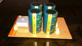
35 V +/- PSU is excellent . 22 000 uF 40 V power supply capacitors are cheap even in computer grade .

Notice I have moved C10 ( as now ) to a 220 pF starting point . COG or NPO ceramic .
Try first R10 as zero ( 0 ) ohms using your ears to judge it's sound . In theroy this is best especailly if ZTX694B is used . It has a gain of 500 which sets Z in as about 1K5 without R10 to assist . That suggests to me R10 is optimum at about 2R . If BD139 R 10 optimum is about 30R . The textbooks say R10 should be 0 . I slightly disagree with them .
The current mirror allows any change to work . It automatically adjusts . Text books say add two resistors . You can if you like . Compared to before it will be better regardless . My experience is you will never equal BCV 61 if you make it yourself from two transistors . Do not think it's low voltage is a problem as the T6 protects it ( 1 V clamp ) . If you wonder could the BCV 61 be made from a diode and and transistor , yes it can . The advantage when op amps is the transistors are easier to make inside a chip than diodes. Also the matching is far better if the same device . I usually don't fit the extra resistors because it reduces the Vce margin . That is usually 0.2 V and the base of T6 might be 0.55V . Even though a current amp I don't want to loose 0.1 V . I took this idea from the 741 op amp ( as did everyone ) . Crimson Electronics UK was where I first saw it about 1980 ( 741 circa 1963 to 67 ) .
The Current mirror will increase the slew rate as none of the current is wasted in a resistor . Not having the swamping resistors ( to BCV pins 3 and 4 , 100 R to -ve 40 V ) will slightly increase the second harmonic distortion which is no bad thing . Do you want the sound bone dry ? If you do add the resistors and build a 4 transistor mirror . R10 becomes mandatory if you do .
C10 has been set high as the gain will be dramatically increased in relative terms . I would expect the optimum to be below 100 pF .
It is possible to use low voltage transistors for T1 and T3 as there is virtually zero voltage gain here . These transistors will give lower DC offset as the gain is high . Strictly regulate the voltage if so . C6 will help protect the transistor on switch on . Personally I would set the voltgae to 35 V .
I now have the fuse in the feedback loop . The Zobel network R17 C 18 might better be connected to the node of R15 R16 . You can keep the capacitor as before if you like .
Nige, the analogy with a race car would stand much better if you had taken it to its full limit.
Yes, it is possible to blow the engine to incredible limits, but for that to be effective and make sense, one also needs to review and upgrade ALL the rest as well. For example, what use tremendous engine power you can't transfer to the road without increasing the size of the tyres? Today, even mass produced cars offer turbo engine efficiency of 130-150 bhp/litre (e.g. Ford, Opel/GM, Volkswagen group, etc), and even neturally aspirated engines are taken to 100 bhp/litre (e.g. Subaru BRZ, Toyota GT86, etc). None of these is an exotic priced vehicle.
Ditto for power amps. If you want it to be a reasonably simple circuit, yet be able to deliver some serious power even into questionable nominally 4 Ohm speakers, then you need to very carefully think it out, and if we assume you will use a better design than the tradional slap together and choke on negative feedback unit, you need to think even more and spend more.
In my view, the basic design platform of what Gost22 wanted is simply a non event, it is sufficiently poor to start with that there's no sense in trying snips here and there to get some mileage from it. Much like a car which you want to tune only to discover that there is no physical space under the bonnet for a turbocharger. It makes more sense to sit down and start again from scratch, still using popular and easily obtainable parts, with a reasonable price tag attached.
Then go for the maximum you can get out of it. Very low THD figures are not likely, given the low voltage power supplies, but well below say 0.1% at rated power, with a low global NFB figure of no more than 26 dB, should be possible. On a trial verson, I managed a 20-20,000 THD figure of less than 0.065%, but in return, the 50 kHz THD was just 0.27%. The internal (without an input filter) slew rate is better than 150 V/uS with a bandwidth of 550 kHz, the effective (i.e. with an input filter with -3 dB at 200 kHz) slew rate is a bit over 80 V/uS. Not a FET or MOSFET in sight, all straight forward bipolars. Output stage is Motorola, 2 pairs of MJ 21193/21194. In fact, with the exception of the input pair, 2SC2240 by Toshiba, the rest of the amp might as well be called a Motorola amp, with MPSA42/92 accounting for much of the amp. Simple, cheap common transistors in handy TO-92 package. But then, Toshiba is the Japanese version of Motorola.
Wanna look-see?
Last edited:
Finally
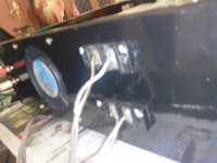
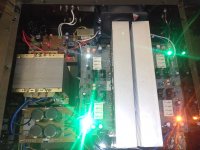
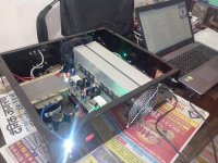
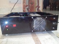
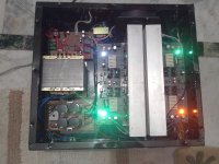
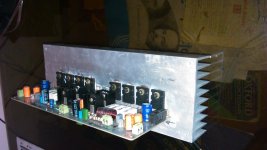
It's been long since I designed my 250W amp.
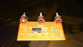
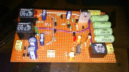
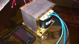
Finished the beast at last. Attached are some pics of the build.
Cheers!!!
It's been long since I designed my 250W amp.
Finished the beast at last. Attached are some pics of the build.
Cheers!!!
Attachments
-
 IMG_20140116_215743.jpg301.8 KB · Views: 205
 -
 IMG_20140116_215705.jpg317.4 KB · Views: 224
 -
 IMG_20140116_215657.jpg357 KB · Views: 201
 -
 IMG_20140116_173247.jpg285.2 KB · Views: 249
 -
 IMG_20140116_173232.jpg306.1 KB · Views: 278
 -
 DSC_0359.jpg197.5 KB · Views: 242
 -
 DSC_0354.jpg285.5 KB · Views: 892
 -
 DSC_0351.jpg208.4 KB · Views: 910
 -
 DSC_0350.jpg212.3 KB · Views: 957
 -
 DSC_0345.jpg188.2 KB · Views: 994
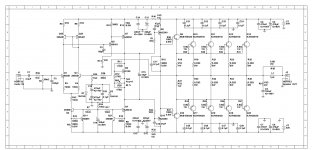
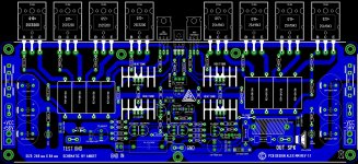
The Signal Ground/Return and the NFB network are shown attached to the Power Ground.
Is that the way you built it?
The signal ground and the NFB ground share the same ground which goes back to the main star ground on the PCB. Infact, lifted ground for the signal and NFB could also be done, it just need a 5~10 ohm resistor which could be mounted down left in place of the jumper.
The pics of the amp shown on post #357, have the PCB's designed by AlexMM(attached).
Regards,
Aniket
Attachments
- Status
- This old topic is closed. If you want to reopen this topic, contact a moderator using the "Report Post" button.
- Home
- Amplifiers
- Solid State
- Simple 100W power amp