Some idea about this :
- look for some short circuit on both IC LA and LC pins
- try another laser / mechanic
Found a short on LA pins 23/24 but that short was on the original shiga as well. Shouldn't be a problem as pin 23 is NC
")
Regards
Now about your selfmounted MKII.
I still didn't get an answer on which transisitor do you use.
Regards,
Tibi
Sorry Tibi.
I didn't understand you were waiting for input, my apologies.
Q1 = Marked PJ66 M3A
With the scope I found that the voltage on collector is 4,6V and when activated it drops to 4,4V.
The only one I know of with a macrolens is on vacation... I can take anothe iPhone photo if it is of any gain.
Regards
Last edited:
Found a short on LA pins 23/24 but that short was on the original shiga as well. Shouldn't be a problem as pin 23 is NC
Regards
23 and 24 should be connected.
Regards,
Tibi
Sorry Tibi.
I didn't understand you were waiting for input, my apologies.
Q1 = Marked PJ66 M3A
With the scope I found that the voltage on collector is 4,6V and when activated it drops to 4,4V.
The only one I know of with a macrolens is on vacation... I can take anothe iPhone photo if it is of any gain.
Regards
This is normal. Q1 get saturated under normal operation and entire laser curent is dictated by Q1Vbe and emitor resistor.
While TOC search you should see a white light with a camera, right above laser lens.
Regards,
Tibi
This is normal. Q1 get saturated under normal operation and entire laser curent is dictated by Q1Vbe and emitor resistor.
While TOC search you should see a white light with a camera, right above laser lens.
Regards,
Tibi
No light - dead...
Regards
Well this is something new.
It never hapen before to have a dead mechanic due laser.
I would susspect: laser protection solder bulb not properly removed (use a multimeter and measure exactly over), ribbon cable twisted or broken, main board connector have short or bad solder.
Regards,
Tibi
It never hapen before to have a dead mechanic due laser.
I would susspect: laser protection solder bulb not properly removed (use a multimeter and measure exactly over), ribbon cable twisted or broken, main board connector have short or bad solder.
Regards,
Tibi
Well this is something new.
It never hapen before to have a dead mechanic due laser.
I would susspect: laser protection solder bulb not properly removed (use a multimeter and measure exactly over), ribbon cable twisted or broken, main board connector have short or bad solder.
Regards,
Tibi
Thanks Tibi. I measured the static protection - no short. I'll wait for the replacement and have high hopes as there is no toroid rumbling around in this shipment
. The rest of your proposals are checked and seems to be in order. Suppose the laser and its circuit is in order. How does the MCU decide when to light the laser or not? What signals does give the input for the decision?Regards
Last edited:

Yes, this is correct. For more detailed info related to miniregs pin assignment vicol audio : Low noise LDO mini regulatorhi tibi,
or this one? just making sure im doing the right install.
Thanks
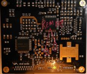
V1, V2, V3, V4 is 8V pad not GND. Anyhow you'll not use this as power input, due your super-regulators will need a higher power supply above 8V depending on the type you use - refer to manufacturer super-reg datasheet.
As mentioned by Danzup, in case V1 and V2 are mounted, respectively L2 and L3 must be removed.
Regards,
Tibi
Last edited by a moderator:
hi tibi,
or this one? just making sure im doing the right install.
Thanks
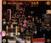
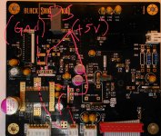
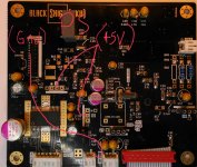
Pin1 of J6 is GND for your superreg !!!!
Middle pin of V1 and V2 print on Shiga is where you connect +5V output from your superreg . Remove L2 and L3 .
Attention !!!! This voltage ( delivered by superreg ) must power on and power off at the same time with V3 and V4 .
Failing to do so and Shiga will not work .
See attached corrected picture .
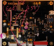
Use that pin for GND of superreg (pin1 of connector J6)
do not connect other wire !
If you do not understand please take pictures and ask here if connection are correct prior to power on Shiga.
Use that pin for GND of superreg (pin1 of connector J6)
do not connect other wire !
If you do not understand please take pictures and ask here if connection are correct prior to power on Shiga.
Attachments
Last edited:
hi guys,
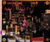
thanks for the support. hopefully i got it right this time. please verify if this is correct.
thanks once again
Yes : this time is correct .This is how must be done.
- Home
- Source & Line
- Digital Source
- Shigaclone MKII Black - The builders Thread