Found the part. its really obscure- its an NEC UPA61A visible on this datasheet Datasheet Archive - Datasheet Search Engine Download The rest is Japanese.
I also found it in an obscure set of databooks I got in Japan in 1988. Attached is a scan of the relevant pages.
I also found it in an obscure set of databooks I got in Japan in 1988. Attached is a scan of the relevant pages.
Attachments
More answers for those that are interested-
The sample clock runs at 64X the input frequency at 1 KHz and below. Above it runs at 12.8 X and then at 25 KHz the clock is 32.652 KHz. At 100 KHz the clock is 130.6 KHz.
The ADC's available when this was made were not particularly exceptional but this seems like the hard way to do it. My FFT (Rockland/Wavetek) which is contemporary to this instrument uses a single chip 8 bit ADC good for 200 KHz sampling.
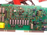
There seems to be no nulling circuit. It seems to tune each of the three notch filters based on the frequency counter. The notch seems to have a flat rejection band about .5% wide or less. This means that the tuning circuit can't introduce harmonic distortion. Its nice to be able to use unlimited numbers of relays. I think after the first stage the opamps are not significant distortion contributors. There is an NE5534 on the first filter PCB. LM318's afterwards. It uses several TL073's. At first I thought that was a typo but they are real, just vanished from TI's datasheets a long time ago. It is a dual opamp with offset trims for both halves.
Even with these ancient opamps I'm getting the equivalent of -115dB THD+N in a 30 KHz band with the matching generator.
The manual will be interesting. I think the direct tuned notch filters times 3 is the real magic here. The rest is good execution. The input amplifier is good but no real breakthrough. The input NJFET pair buffers into the bipolar differential with current mirror loading. They have made an effort to keep the voltage across the JFET pair constant as the signal swings. This will reduce input capacitance and probably make the input more linear. Then the rest is just good practice. I know I have seen this before somewhere.
The amplifier circuits in the AR590 seem to be the same, with the same complement of devices, except the JFETs are singles instead of a dual.
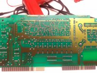
Below are pictures of the front and back of the input PCB.
The sample clock runs at 64X the input frequency at 1 KHz and below. Above it runs at 12.8 X and then at 25 KHz the clock is 32.652 KHz. At 100 KHz the clock is 130.6 KHz.
The ADC's available when this was made were not particularly exceptional but this seems like the hard way to do it. My FFT (Rockland/Wavetek) which is contemporary to this instrument uses a single chip 8 bit ADC good for 200 KHz sampling.
There seems to be no nulling circuit. It seems to tune each of the three notch filters based on the frequency counter. The notch seems to have a flat rejection band about .5% wide or less. This means that the tuning circuit can't introduce harmonic distortion. Its nice to be able to use unlimited numbers of relays. I think after the first stage the opamps are not significant distortion contributors. There is an NE5534 on the first filter PCB. LM318's afterwards. It uses several TL073's. At first I thought that was a typo but they are real, just vanished from TI's datasheets a long time ago. It is a dual opamp with offset trims for both halves.
Even with these ancient opamps I'm getting the equivalent of -115dB THD+N in a 30 KHz band with the matching generator.
The manual will be interesting. I think the direct tuned notch filters times 3 is the real magic here. The rest is good execution. The input amplifier is good but no real breakthrough. The input NJFET pair buffers into the bipolar differential with current mirror loading. They have made an effort to keep the voltage across the JFET pair constant as the signal swings. This will reduce input capacitance and probably make the input more linear. Then the rest is just good practice. I know I have seen this before somewhere.
The amplifier circuits in the AR590 seem to be the same, with the same complement of devices, except the JFETs are singles instead of a dual.
Below are pictures of the front and back of the input PCB.
Attachments
There seems to be no nulling circuit. It seems to tune each of the three notch filters based on the frequency counter. The notch seems to have a flat rejection band about .5% wide or less. This means that the tuning circuit can't introduce harmonic distortion. Its nice to be able to use unlimited numbers of relays. I think after the first stage the opamps are not significant distortion contributors. There is an NE5534 on the first filter PCB. LM318's afterwards. It uses several TL073's. At first I thought that was a typo but they are real, just vanished from TI's datasheets a long time ago. It is a dual opamp with offset trims for both halves.
Even with these ancient opamps I'm getting the equivalent of -115dB THD+N in a 30 KHz band with the matching generator.
All good stuff. Very helpful.. collaborates other tests here. The view I have of the notch -- it is probably in the neighborhood of 0.1% to get the accuracy it seems to have on 2H and 3h that i have focused on.
Those devices (especially the TL0xxx type opamps) are the ones i want to change but not for distortion reasons but to lower the noise so that at the monitor output of the residuals, we can get harmonic readings to an even lower level without noise obscuring the harmonic levels.
Thx-RNMarsh
To A Good Home...
 .
.
I got an Ebay notification of a new ShibaSoku item listing on my Ebay phone app...when I checked it was already gone .
I was going to tell Mr Marsh about it....scout's honour .
Anyway....two days ago I got hold of an AWA F242A auto nulling D&N test set....it came out of the local airforce and looks quite unused.
It seems to be very microphonic on -80dBm range level meter function...I will open it tonight and have a look.
Part of my reason for grabbing it is to use it as a pre usb soundcard notch filter for spectral measurements.
Anybody have experience/advice/improvements regarding this meter ?.

AWA F242A User/Service Manual.pdf
Thanks in advance, Dan.
I'm glad one of you guys got itToo late- I just bought it. I'll scan it and make the file available when I get it. Should be very interesting. He relisted it instantly. . .
.I got an Ebay notification of a new ShibaSoku item listing on my Ebay phone app...when I checked it was already gone
.I was going to tell Mr Marsh about it....scout's honour
.Anyway....two days ago I got hold of an AWA F242A auto nulling D&N test set....it came out of the local airforce and looks quite unused.
It seems to be very microphonic on -80dBm range level meter function...I will open it tonight and have a look.
Part of my reason for grabbing it is to use it as a pre usb soundcard notch filter for spectral measurements.
Anybody have experience/advice/improvements regarding this meter ?.
AWA F242A User/Service Manual.pdf
Thanks in advance, Dan.
There's some Nyquist tricks that can be used. Allowing the sampler to alias. Since this is synchronized periodic sampling I wonder if the sampling could be spread over several cycles at high frequencies. The ADC could be steered to the correct sample position over a number of cycles. This assumes the harmonics are constant from one sample to the next and the wave form is unchanged. It could be possible to use a constant 64x rate through the entire bandwidth say in multiples of 192kHz. For example the highest frequency at 192k is 3KHz. 6K would sample over two cycles and so on.
I'm glad one of you guys got it
I got an Ebay notification of a new ShibaSoku item listing on my Ebay phone app...when I checked it was already gone
I was going to tell Mr Marsh about it....scout's honour
Anyway....two days ago I got hold of an AWA F242A auto nulling D&N test set....it came out of the local airforce and looks quite unused.
It seems to be very microphonic on -80dBm range level meter function...I will open it tonight and have a look.
Part of my reason for grabbing it is to use it as a pre usb soundcard notch filter for spectral measurements.
Anybody have experience/advice/improvements regarding this meter ?.
View attachment 370378
AWA F242A User/Service Manual.pdf
Thanks in advance, Dan.
Which ShibaSoku model was it? eBay has quit a few of their brand but mostly video gear.
The unit you bought looks to be a good candidate for a notch filter. If its cheap enough and saves time by not building something, thats great for me, too. I dont have any experience with that one. Let us know how well it worked for you.
Thx-RNMarsh
Which ShibaSoku model was it? eBay has quit a few of their brand but mostly video gear.
The unit you bought looks to be a good candidate for a notch filter. If its cheap enough and saves time by not building something, thats great for me, too. I dont have any experience with that one. Let us know how well it worked for you.
BTW - there is a nice Panasonic VP-7723 for sale on ebay that someone should grab.
Thx-RNMarsh
yes, that is very true for the nuts and fanatics...
The 7723 is typically .0005%. The price is right.
But if/when the 7722 or a newer 7725 show up on eBay they are, of course, THEE ones to get but they sell for 2-3 times more and typically resolve to .0001%. The 7722 and 7725 come standard with GPIB also. The 7722 also has IMD built-in.
[THD Nut that i am --> I also have in my stock inventory a VP-7723 and a VP-7722. The 7722A is great. The 7723 has different filters/noise weighting and feature set that is useful for certain DUT like FM tuners, tape decks and turn tables, for xample]
Thx-RNMarsh
Last edited:
I've mentioned this privately to some who are in this thread, but I'll throw up the balloon anyhow.
I have a VP-7725 Panasonic that is partially crippled and whose calibration is unknown (although it seems plausible). I managed to tzappp the input on one channel. The guts are complex, and the box is computer controlled to add to the mayhem. Not an easy unit to figure out quickly.
Having tried ALL of the usual and possible avenues (Panasonic, Levear, distributors, repair depots, ebay sellers, etc...) I am at a loss for either a users manual (very useful) or a *schematic* or service manual. Anyone who may have a way to obtain one, please PM me!!
Anyone with contacts in China with Levear or in Japan with Panasonic would be extremely useful.
Thanks.
_-_-bear with crippled VP-7725
Here is a link that will give the experience without actually owning the analyzer (if you read Japanese) ‚`‚•‚„‚‰‚��@‚`‚Ž‚�‚Œ‚™‚š‚…‚’�@‚u‚o�|‚V‚V‚Q‚R‚`�@‚u‚o�|‚V‚V‚Q‚R‚a�@‚u‚o�|‚V‚V‚Q‚R‚c
Lots of other interesting links here: Index of /amp-etc/etc-etc
Lots of other interesting links here: Index of /amp-etc/etc-etc
Last edited:
Those devices (especially the TL0xxx type opamps) are the ones i want to change but not for distortion reasons but to lower the noise so that at the monitor output of the residuals, we can get harmonic readings to an even lower level without noise obscuring the harmonic levels.
Thx-RNMarsh
Doing some arcane calculations etc. I think the input of the 725 has a noise level of around 5.6 nV/rtHz. I'm not sure of the calculations and measurements yet. If so the limit may be the input circuit- the dual JFET + bipolars. And maybe the input attenuator. On the three volt input level the series resistor limits the noise to 4.9 nV/rtHz. Its possible to get lower noise JFETs and bipolars but I don't know if the circuit would still function the same with the larger area devices.
This is a great tool for figuring out thermal noise: Thermal Noise Calculator
Which ShibaSoku model was it? eBay has quit a few of their brand but mostly video gear.
The unit you bought looks to be a good candidate for a notch filter. If its cheap enough and saves time by not building something, thats great for me, too. I dont have any experience with that one. Let us know how well it worked for you.
Thx-RNMarsh
I was referring to the service manual that 1Audio grabbed.
I am building a test/compare interface box, then I can try it out properly.
Dan.
Re. AD725 -- There appears to be gain in the path with HP/LP filters and later stages where the monitor output is located..... they add and amplify the noise. They use the old TL0xx types and others of the era. I believe it is from the filters to the monitored output port itself taht is noisy.... rather than the analyzer portion.
But, the design/circuitry using the dual jFET input stage would be nice to know its design as the distortion must be really, really low, as well.
THX-RNMarsh
But, the design/circuitry using the dual jFET input stage would be nice to know its design as the distortion must be really, really low, as well.
THX-RNMarsh
Last edited:
Bear - I'll buy your blown up VP-7725 from you, cheap
[Ouch! Sorry. couldnt help myself]
But seriously, I would also try to find the 7722 circuit as I think they are the same/similar.. just mostly changed the red led displays to LCD screen etc for the newest one (7725).
-RM
[Ouch! Sorry. couldnt help myself]
But seriously, I would also try to find the 7722 circuit as I think they are the same/similar.. just mostly changed the red led displays to LCD screen etc for the newest one (7725).
-RM
Last edited:
Lots of other interesting links here: Index of /amp-etc/etc-etc
Interesting how they are also comparing one machine against another to see what each show for a measurement result.
-RM
Found the part. its really obscure- its an NEC UPA61A visible on this datasheet Datasheet Archive - Datasheet Search Engine Download The rest is Japanese.
I also found it in an obscure set of databooks I got in Japan in 1988. Attached is a scan of the relevant pages.
Thanks for finding the information on the uPA61A. I searched the internet with no luck. I also had trouble finding the TL083 which I had never come across before.
It completes my schematic. Thanks also for the pictures of the board which at first glance look identical to mine.
- Home
- Design & Build
- Equipment & Tools
- ShibaSoku Automatic Distortion Analyzer