I own two of them. use the VP-7722A frequently.
-RM
I hate to do this, but what oscilloscope are you using?
I hate to do this, but what oscilloscope are you using?
Yes, I have several. Portable is a TEK TDS 3032 with options. I have 7000 series also with numerous plug-ins. And HP-54522A. 300, 500, 500MHz respectively.
THx-RNMarsh
What is the interest? I believe Richard has an older HP digital and some others. (I have really too many, 4 on the bench with 5 spares and a 7L12 in a storage frame).
Because it is time to run up the price of another undervalued piece of test equipment! HP 54542A 4 channel 500 MHz scopes are going for as little as $400.00 on eBay.
A bit old but mine is great. I have been easily measuring things I couldn't even see before.
It also does FFTs. Only downside is to get screen prints it is best done with floppy discs.

Simon,
What's a floppy disk?
IF I knew the above, do they really flop?
Cheers,
Sync
Yes they really do flop.
Because it is time to run up the price of another undervalued piece of test equipment! HP 54542A 4 channel 500 MHz scopes are going for as little as $400.00 on eBay.
A bit old but mine is great. I have been easily measuring things I couldn't even see before.
It also does FFTs. Only downside is to get screen prints it is best done with floppy discs.
Does the HP use the HP unix formatted disks? I had to deal with those for a while on a network analyzer. GPIB gave a way out of that purgatory.
Does the HP use the HP unix formatted disks? I had to deal with those for a while on a network analyzer. GPIB gave a way out of that purgatory.
Text and two other options I don't rember. But I use tif.
Did post one on the blowtorch thread a few days ago.


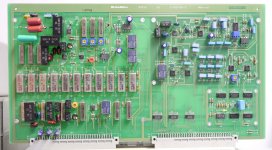
I replaced the feedback amp for the first notch filter on the AM51B.
The original part is a NJM5534M by JRC in a DMP-8 package. It is designated U8 on the upper left portion of board assembly A2.
The replacement was an OPA1611 in a SOIC-8 package. It'll fit just fine on the original PCB footprint, no modifications are necessary.
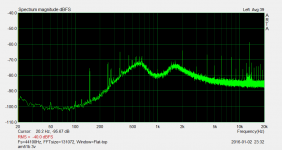
The distortion on the second harmonic was reduced by about ~7dB, the 2nd now reads -139dB on the meter using the built in oscillator.
I need to investigate the funny business going on at ~13kHz, I think it's poor ground routing, oh boy...
The original part is a NJM5534M by JRC in a DMP-8 package. It is designated U8 on the upper left portion of board assembly A2.
The replacement was an OPA1611 in a SOIC-8 package. It'll fit just fine on the original PCB footprint, no modifications are necessary.
The distortion on the second harmonic was reduced by about ~7dB, the 2nd now reads -139dB on the meter using the built in oscillator.
I need to investigate the funny business going on at ~13kHz, I think it's poor ground routing, oh boy...
Attachments
What range do you have the analyzer set to -90dB, -100dB?
And what sound card are you using?
I usually have something going on around 15kHz to 16 KHz. It's ingress into the EMU0204. It comes and goes from day to day. So some electronics near by.
The cable modem I used to have had an 18MHz burst tone that got into all my measurements. The IM from that worked ist way down into the audio spectrum. Drove me nuts. Thne one day I noticed a 63MHz low level on my scope and the audio spectrum on the FFT was a lot noisier. This went on for a few days until one day I noticed it was gone. I wasn't listening to music that day. It turned out it was my old Sansui amp that was oscillating at 63MHz on one channel.
I didn't think there were power transistor that could go that fast from back then.
It's possible to clean the spectrum up a lot more with these analyzers.
Last edited:
I replaced the feedback amp for the first notch filter on the AM51B.
The original part is a NJM5534M by JRC in a DMP-8 package. It is designated U8 on the upper left portion of board assembly A2.
The replacement was an OPA1611 in a SOIC-8 package. It'll fit just fine on the original PCB footprint, no modifications are necessary.
The distortion on the second harmonic was reduced by about ~7dB, the 2nd now reads -139dB on the meter using the built in oscillator.
I need to investigate the funny business going on at ~13kHz, I think it's poor ground routing, oh boy...
Is that that ground doing a complete loop around the perimeter of the PCB?
If so that's a no no in PCB design. Besides looping the ground it also forms a dipole antenna.
David,
If we see these ground loops on boards such as this, whats the best
method to un-loop, un-dipole antenna them?
Cut trace and solder in star on the board for the other ground points?
Make a ground bus with solid copper wire and feed the other grounds
to it?
Thinking out loud here.
Cheers,
Sync
If we see these ground loops on boards such as this, whats the best
method to un-loop, un-dipole antenna them?
Cut trace and solder in star on the board for the other ground points?
Make a ground bus with solid copper wire and feed the other grounds
to it?
Thinking out loud here.
Cheers,
Sync
I just break the loop. No rearrangement. But first determine if it really matters.
What on the board? What gains are pressent.
If the loop is on a board with 30dB + of gain or more then there may be ab issue.
If it on a digital board then probably not an issue.
The earlier Shibasoku deigns didn't do these ground loops on the boards. So it's not the same people doing the design.
The loop might just be for the grounded back pane.l In which case then it doesn't matter since the back panel will close the loop. See if there are any parts/circuits using the ground.
- Home
- Design & Build
- Equipment & Tools
- ShibaSoku Automatic Distortion Analyzer