My guess is that you don't need the extra source follower output.
Hi daanve - I've given your suggestion more thought and ran some LTSpice simulations, which actually suggest a lower output impedance is achieved when taken from the DN2540 source, which surprised me. I decided to act on it and bypassed the source follower PCB in the phono stage.
Does it sound better? I can't say, but the sound is still very good, so I may even make the change permanent after taking some real-world measurements. Thanks for pointing it out, will look into it further.

The schematic is good and worth tweaking.
You might take advantage of the first stage low output impedance as well and try a low impedance passive riaa (~5k for R7); capacitors will get bigger though.
Low impedance equalization is regarded to sound better (600 ohm LCR networks ....).
All depends how far you want to go.
You might take advantage of the first stage low output impedance as well and try a low impedance passive riaa (~5k for R7); capacitors will get bigger though.
Low impedance equalization is regarded to sound better (600 ohm LCR networks ....).
All depends how far you want to go.
Thanks! They are Pete Millet's filament supplies, they feed DC to the D3a / EF86 heaters such that only DC in makes it to the phono chassis.
I can see how a common mode choke there makes total sense with such a low level source like a phono cartridge. Not for 120hZ ripple filtering, but to quash out or lessen any 60hZ getting still riding on the filaments.
A year-and-a-half later and I am planning to rework this phono stage. I've got the LCR RIAA bug in my ear, so I'd like to give it a try. I have a collection of D3a and E810F, and I've also collected eight or so pairs of E55L, will be using them in this design.
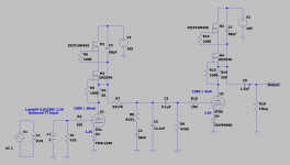
Here is a draft schematic of what I have in mind.

From start to finish, an explanation of the circuit.
1) Balanced inputs once again (3-pin XLR), same Lundahl LL9226XL MC SUT wired for 1:10, balanced primary, single-ended secondary
2) Battery biased, triode strapped D3a or E810F first gain stage, CCS loaded and wired as a hybrid mu follower to drive the 7.5K LCR RIAA, capacitor coupled to the RIAA filter
3) 7.5K LCR RIAA using Dave Slagle's inductors. The chokes are tapped at multiple points so RIAA compliance can be measured and adjustments made
4) Cathode biased, triode strapped E55L output stage, CCS loaded and wired as a hybrid mu follower, capacitor coupled outputs
Again, the power supply will be in a separate chassis with all AC isolated, DC to the phono chassis via an umbilical. I'm now reasonably proficient in PCB design as well as designing LDO regulator circuits, so will use my own heater regulator using the LT3083 (fortunately still have some left over from another project). Will likely also design portions of the RIAA onto a PCB with trimmers for ease of adjustability.
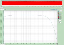
I've tuned the RIAA filter in simulation, here is the output frequency response, around 67dB of gain.

That's the plan for now, subject to change, might make a new thread when it is finalized and I start building it.
Here is a draft schematic of what I have in mind.
From start to finish, an explanation of the circuit.
1) Balanced inputs once again (3-pin XLR), same Lundahl LL9226XL MC SUT wired for 1:10, balanced primary, single-ended secondary
2) Battery biased, triode strapped D3a or E810F first gain stage, CCS loaded and wired as a hybrid mu follower to drive the 7.5K LCR RIAA, capacitor coupled to the RIAA filter
3) 7.5K LCR RIAA using Dave Slagle's inductors. The chokes are tapped at multiple points so RIAA compliance can be measured and adjustments made
4) Cathode biased, triode strapped E55L output stage, CCS loaded and wired as a hybrid mu follower, capacitor coupled outputs
Again, the power supply will be in a separate chassis with all AC isolated, DC to the phono chassis via an umbilical. I'm now reasonably proficient in PCB design as well as designing LDO regulator circuits, so will use my own heater regulator using the LT3083 (fortunately still have some left over from another project). Will likely also design portions of the RIAA onto a PCB with trimmers for ease of adjustability.
I've tuned the RIAA filter in simulation, here is the output frequency response, around 67dB of gain.
That's the plan for now, subject to change, might make a new thread when it is finalized and I start building it.
My one thought is about the D3A miller capacitance. I designed and built a phono stage using one on the input and the miller capacitance affected SUT performance and reflected quite a large capacitance back to the cartridge. Figure somewhere north of 300pF Cmiller, and multiply that by the square of the SUT turns ratio and that's what your cartridge will see. LOMC are supposedly immune to fairly large capacitances across their output, but in fact I found this wasn't entirely true. I achieved "acceptable" performance but thought the end result was a bit euphonic and soft sounding, really hurt dynamics.
An 8X SUT will multiply the Cmiller by 64x and the cartridge then sees about 19nF, 16X SUT the situation is much worse at roughly 77nF.
Possibly considering a pentode configuration on the input might be worthwhile.
An 8X SUT will multiply the Cmiller by 64x and the cartridge then sees about 19nF, 16X SUT the situation is much worse at roughly 77nF.
Possibly considering a pentode configuration on the input might be worthwhile.
My one thought is about the D3A miller capacitance. I designed and built a phono stage using one on the input and the miller capacitance affected SUT performance and reflected quite a large capacitance back to the cartridge. Figure somewhere north of 300pF Cmiller, and multiply that by the square of the SUT turns ratio and that's what your cartridge will see. LOMC are supposedly immune to fairly large capacitances across their output, but in fact I found this wasn't entirely true. I achieved "acceptable" performance but thought the end result was a bit euphonic and soft sounding, really hurt dynamics.
An 8X SUT will multiply the Cmiller by 64x and the cartridge then sees about 19nF, 16X SUT the situation is much worse at roughly 77nF.
Possibly considering a pentode configuration on the input might be worthwhile.
Thanks Kevin, since my current phono uses a similar triode D3a input with 1:10 SUT, I'll see if I can dig up my original measurements, or I'll repeat them. If it's an issue, I'll investigate pentoded D3a.
I need to re-evaluate my measurement setup on the second go around. I have some test records with FR sweeps along with a inverse RIAA filter I put together. At one point I was also applying the inverse RIAA in software via REW. Can I ask how you've checked bandwidth on your MC phono designs?
Hi LordGwyn,Thanks Kevin, since my current phono uses a similar triode D3a input with 1:10 SUT, I'll see if I can dig up my original measurements, or I'll repeat them. If it's an issue, I'll investigate pentoded D3a.
I need to re-evaluate my measurement setup on the second go around. I have some test records with FR sweeps along with a inverse RIAA filter I put together. At one point I was also applying the inverse RIAA in software via REW. Can I ask how you've checked bandwidth on your MC phono designs?
It's been a few years since I last designed and built a phono stage and I generally restrict my measurements to 20Hz - 20kHz. I use an inverse equalizer that was made by GenRad decades ago - I occasionally check its accuracy. I suppose I should write a script for my RTX (Virtins) to generate the inverse EQ directly.
My biggest problems are always in the bottom octave because I use passive EQ with rather low impedances and always under appreciate the interactions between the coupling cap between the first stage and the EQ.
I try to simulate the cartridge source impedance with a resistive divider and discovered that I could see the effects of the phono stage input impedance as modified by the SUT and phono stage input impedance. (R + Cstray + Cmiller). I was surprised at what happened to the FR right at the cartridge - not sure this is much considered these days.
Scott Wurcer posted some formulas that I tested, tho I don't remember how. IIRC he posted them in the Test LP thread. Don't know if the would work with RTX.I suppose I should write a script for my RTX (Virtins) to generate the inverse EQ directly.
See here for coefficients.
https://www.diyaudio.com/community/threads/error-in-d-self-riaa.203706/post-2865323
https://www.diyaudio.com/community/threads/error-in-d-self-riaa.203706/post-2865323
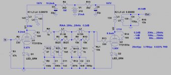
This is my E.A.R MC3 (4R input) stepup + 12AX7 (really 5751) phono FR measuring.
12AX7 has about 200pF Miller capacitance.
View attachment 1054127
I wouldn't worry about that.
Thanks for the data point, I hadn't noticed any HF rolloff on my original build, but I will remeasure to confirm. What is the step up ratio on the E.A.R. MC3 for that measurement?
Hi LordGwyn,
It's been a few years since I last designed and built a phono stage and I generally restrict my measurements to 20Hz - 20kHz. I use an inverse equalizer that was made by GenRad decades ago - I occasionally check its accuracy. I suppose I should write a script for my RTX (Virtins) to generate the inverse EQ directly.
My biggest problems are always in the bottom octave because I use passive EQ with rather low impedances and always under appreciate the interactions between the coupling cap between the first stage and the EQ.
I try to simulate the cartridge source impedance with a resistive divider and discovered that I could see the effects of the phono stage input impedance as modified by the SUT and phono stage input impedance. (R + Cstray + Cmiller). I was surprised at what happened to the FR right at the cartridge - not sure this is much considered these days.
I'll keep this in mind, simulating the cartridge is not something I've attempted. To see the cartridge's interaction, I used a FR sweep from a test LP, but lots of room for error there. For adjusting the RIAA EQ, I bypassed the SUT with my signal generator for the more favorable 47K input impedance, so SUTs effects were not included. I would like to put together a more robust measurement setup such that I can simulate the cartridge's effect using a signal generator, I haven't started digging into what that would look like yet, practically speaking.
1:30What is the step up ratio on the E.A.R. MC3 for that measurement?
E55L with its ~600 ohm output impedance is a great choice for this second position.A year-and-a-half later and I am planning to rework this phono stage. I've got the LCR RIAA bug in my ear, so I'd like to give it a try. I have a collection of D3a and E810F, and I've also collected eight or so pairs of E55L, will be using them in this design.
Here is a draft schematic of what I have in mind.
View attachment 1054062
From start to finish, an explanation of the circuit.
1) Balanced inputs once again (3-pin XLR), same Lundahl LL9226XL MC SUT wired for 1:10, balanced primary, single-ended secondary
2) Battery biased, triode strapped D3a or E810F first gain stage, CCS loaded and wired as a hybrid mu follower to drive the 7.5K LCR RIAA, capacitor coupled to the RIAA filter
3) 7.5K LCR RIAA using Dave Slagle's inductors. The chokes are tapped at multiple points so RIAA compliance can be measured and adjustments made
4) Cathode biased, triode strapped E55L output stage, CCS loaded and wired as a hybrid mu follower, capacitor coupled outputs
Again, the power supply will be in a separate chassis with all AC isolated, DC to the phono chassis via an umbilical. I'm now reasonably proficient in PCB design as well as designing LDO regulator circuits, so will use my own heater regulator using the LT3083 (fortunately still have some left over from another project). Will likely also design portions of the RIAA onto a PCB with trimmers for ease of adjustability.
I've tuned the RIAA filter in simulation, here is the output frequency response, around 67dB of gain.
That's the plan for now, subject to change, might make a new thread when it is finalized and I start building it.
Would simplify the requirements on a transformer output compared with the usual 2k Rp types, if you ever decided to go that way.
E55L with its ~600 ohm output impedance is a great choice for this second position.
Would simplify the requirements on a transformer output compared with the usual 2k Rp types, if you ever decided to go that way.
Thanks! I have another draft of this design that is completely transformer coupled - 1:1 IST between the D3a and the RIAA as well as a 1:1 OPT loading the E55L. Could still consider it, but it would be one expensive project. Using Dave Slagle's inductors and transformers, I'd be looking at something like $1,900 USD worth of iron
I have Dave's transformers and inductors for years .... but haven't enough free time. :-(
View attachment 1054295
You must be a busy guy @euro21 ! You can send them to me
Here is my transformer coupled version. Maybe I will change my mind and save the money for it.
Last edited:
Over the next couple months, I am finally going to be building my Slagle LCR phono stage. Dave is winding me some MC SUTs in a couple weeks, so the build will use those in addition to two pairs of 1:1 transformers and his LCR inductors. I have been collecting tubes / parts for this project for a few years given the cost. I have some 15-20 pairs of D3a and E55L tubes which should do the trick.
Here are some parts I will be using, NOS ceramic magnoval sockets and Cinch shielded 9-pin sockets. It will be a two-chassis build.

Here is the most recent schematic. D3a will be battery biased through the MC SUT secondary, E55L cathode biased.

I'll probably show the completed design, measurements and some of the build process in a separate thread when it's done. Right now I am working on the layout and chassis design in AutoCAD.
Here are some parts I will be using, NOS ceramic magnoval sockets and Cinch shielded 9-pin sockets. It will be a two-chassis build.
Here is the most recent schematic. D3a will be battery biased through the MC SUT secondary, E55L cathode biased.
I'll probably show the completed design, measurements and some of the build process in a separate thread when it's done. Right now I am working on the layout and chassis design in AutoCAD.
- Home
- Amplifiers
- Tubes / Valves
- Sharing my Completed Tube MC Phono - D3a / EF86 / FET Hybrid

