 On this channel:
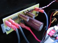
Now I got rewarded for making a easy serviceable layout, replaced the R in the psu, unhooked the pcb and replaced the source resistors on the current source (5x1R5 0,6W in paralell = 0R3 3W) 15min later, I was up and running again  Other channel with psu:
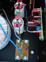
Other channel with psu:Attachments
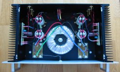
Mad_K said:The whole picture
beautiful work, Mad_K
Inside Mad_K SEWA amp
I am think of buying me a Nikon Coolpix digital camera.
how did you take those photos?
what lighting did you use?
what is your camera?
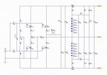
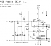
djk said:I have a very nice 20" monitor, and I cannot see any details in your schematic.
Maybe you are not looking at correct place.
I think it is a perfectly alright schematic.
It is in Post #40 Schematic PDF
the onwards posts show pcb and layout and power supply
SEWA Schematic PDF download
Attachments
lineup said:
beautiful work, Mad_K
Inside Mad_K SEWA amp
I am think of buying me a Nikon Coolpix digital camera.
how did you take those photos?
what lighting did you use?
what is your camera?
Thanks, lineup
I took the photos with my ancient canon powershot A10 1,3Mpx crappy old thing. There are cellphones with better cameras these days. No special lighting, just daylight. If I could afford it I would buy a canon EOS350D and a tripod.
Tyimo said:Is it possible to operate your SEWA V1 with higher PSU voltage than 22V?
I have a "nice big fat" 2*24V torroid and I would like to use it.
Main issue is to the COOLING. As always when we are talking CLASS A.
I think Mad_K is using 0.5 W/C heatsinks.
That is rather BIG heatsink.
As long as you can cool amplifier,
and have a stronger power supply
EVERYTHING will be BETTER.
with higher voltage transistor have more 'workspace' and wont 'clip' because of reaching max voltage
you will have margins
transistor will work more linear = a bit lower distortion
it is a fact that an amplifier can not produce any power
that is,
a '10 Watt amplifier' can not deliver anything
unless it has a supply of power connected
all the power comes from POWER SUPPLY
so, amp will never be stonger than power supply
it will always be a little weaker than power supply
( because a bit of power is lost in amp )
Bottomline:
An amplifier is never better than its power supply.
It will have more outputpower in 8 ohms, but will be current limited with a 4 ohm speaker with the same bias current. With 2A bias, you will be limited to 8W with a 4 ohm speaker. You can build it, then crank up the bias later if your heatsinks are up to it I wouldn't go much above 3A though (R12-16=1 ohm) as the dissipation from the mosfet will be hard to handle (45W each).
I wouldn't go much above 3A though (R12-16=1 ohm) as the dissipation from the mosfet will be hard to handle (45W each). Bass control
Hi there,
I would like to build this amp in these days.
(Acturately, I had built PF99 and obtained very good result on mid-high range of sound)
I have two TR with sec 0-30V, so the regulated voltage will be 42V.
But I will limit the bias current < 3A.
How does this configuration sounds? Any comment??
Furthermore, how about the BASS control of SEWA Rev.1 ?
I'm also thinking of adding voltage regulators for input bias, or for the CCS (between R5/R6), does this helps?
(Sorry, a lot of questions)
And, to save energy, the inductors maybe used to replace the CCS...
The bass is very good, considering that it is a single ended, no feedback design. 42V and 3A is dangerously close to the limitations of the fet's  Unless you've got HUGE heatsinks or watercooling I would consider a LC (+LC) or a regulated supply to get the rails somewhere around 30V with 3A bias. I don't think you will gain much with IC regs in this circuit. If you go the inductor CCS route you're on your own
Unless you've got HUGE heatsinks or watercooling I would consider a LC (+LC) or a regulated supply to get the rails somewhere around 30V with 3A bias. I don't think you will gain much with IC regs in this circuit. If you go the inductor CCS route you're on your own - Status
- This old topic is closed. If you want to reopen this topic, contact a moderator using the "Report Post" button.
- Home
- Amplifiers
- Pass Labs
- SEWA - Seven Watt Amplifier