one stage amp
Sorry for the late replay. I have been tryingen to make a better sch. of my amp. But my screen cap is not verry god.
So here is a link for down load of the sch.:
http://rapidshare.de/files/14371438/Cap128.jpg.html (550Kb)
If anyone is welling to helpe my, please poste the pic. So it can seen on this forum.
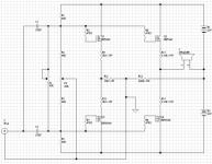
The amp is one stange whit voltages gain, low output imp. and no feedback. It has a real nice sound, much like a single ended tube amp.
I hope you can use it.
Regards
Frank
Sorry for the late replay. I have been tryingen to make a better sch. of my amp. But my screen cap is not verry god.
So here is a link for down load of the sch.:
http://rapidshare.de/files/14371438/Cap128.jpg.html (550Kb)
If anyone is welling to helpe my, please poste the pic. So it can seen on this forum.
The amp is one stange whit voltages gain, low output imp. and no feedback. It has a real nice sound, much like a single ended tube amp.
I hope you can use it.
Regards
Frank
Tyimo said:Yes!
That one never made it, sorry. But the circuit is so simple, it can easily be done p2p. A pcb is really superflous. If you want to make the switch between OTA 3,5 Rev.0 and SEWA Rev.1 as easy as possible (and plan on using the pcb layout provided) you can simply print the layout and use it as a guide to drill the heatsink. Then do OTA3,5r0 p2p, later you can swap without having to redrill the heatsink. However, if you insist, I do have a pcb layout for OT3,5r0 that fits in the same holes, as seen on the pictures in the OTA thread
")
Re: one stage amp
Here is your MOSFET amplifier.
In attachment.
I had to do some image work
Maybe you can use schematic, if you start a new topic about your amplifier.
This topic is about Mad_K amplifier SEWA.
Frank40 said:
I have been trying to make a better schematic of my amp.
If anyone is welling to help my, please post the pic.
So it can be seen on this forum.
The amp is one stage with voltages gain, low output imp.
No feedback.
It has a real nice sound, much like a single ended tube amp.
Here is your MOSFET amplifier.
In attachment.
I had to do some image work
Maybe you can use schematic, if you start a new topic about your amplifier.
This topic is about Mad_K amplifier SEWA.
Attachments
Thanks Mad!
One more question:
What is the situation with the phase in your SEWA V1?
I mean: source-follower circuits doesn't change the phase, but if I use the BOZ preamp that change the phase need I invert the speaker + and - connections in the SEWA output?
With my BOZ+ZenLite it is not problem because both amp are phase shifter.
Greets:
Tyimo
Tyimo; you are right. SEWA/source followers are non inverting, so you will have to invert the speaker terminals to have absolute phase correct when driven from BOZ.
Frank; it's ok, but I think it is better to stay on topic, or else things may get very confusing (as I've already managed by shifting names on my designs)
Frank; it's ok, but I think it is better to stay on topic, or else things may get very confusing (as I've already managed by shifting names on my designs)
Tyimo; You can do that if you want, but it doesn't really matter as Q2 is simply a current source. I use the same type as it is practical, but if you have both types I would probably do it like you described to save the hard to get 044's
ACK2005; SEWA is set up to give 7WRMS into both 4,6 and 8 ohm loads. If 7W is enough on 87dB speakers depends a lot on your listening habits and listening room. I would recommend a speakers from 93dB and upwards. That being said I have lived with ~87dB speakers and 5W amplifiers over long periods of time..
edit: if you build it with 30V rails and 2,5-3A bias you will be able to get about twice the outputpower from the design. I think this will be more suitable for your speakers. This requires very good thermal management though
Hi Mad!
Thanks!
How can I bias the SEWA V.1 to 2,5-3A, if I use 30V rails?
Change R12-R16 to near 1 ohm?
Tyimo
Thanks!
It is the reason why I asked.I would probably do it like you described to save the hard to get 044's
How can I bias the SEWA V.1 to 2,5-3A, if I use 30V rails?
Change R12-R16 to near 1 ohm?
Tyimo
Tyimo said:
How can I bias the SEWA V.1 to 2,5-3A, if I use 30V rails?
Change R12-R16 to near 1 ohm?
Tyimo
You got it. Bias is BE drop of Q3 (0,6V) divided by the paralelled value of R12-16. Say you want 2,5A. 0,6V/2,5A=0,24ohm. 0,24*5=1,2ohm for R12-16.
You also need to change R1 to 5K6 to get the DC operating point just right as I said in post#72
hi
>would consider a LC (+LC) or a regulated supply to get the rails >somewhere around 30V with 3A bias.
Well, how about parallel MOSFET 2A x 2 (for Q1 and Q2 both)?
So, there will be four transistors.
For two parallelized MOSFETs, is it better to use two sets of BC550+R12~R16, one for each MOSFET? or,to use one set of BC550+R12~R16 for both MOSFETs?
I may add a switch to select the current flow through CCS.
I love that design !
It seems like the heatsinking is modest - which I think is good, not to have to have some - anvils - attached to the case. It is because of the fan ventilation you were able to get by with those heatsinks, I think ?
I find myself planning to avoid complex designs, it seems there is no reason for it, since 5, 10, 20 watts can be had with good Class A, and since I plan to use efficient speakers.
And yet I was surprised how much volume a flea powered (about one half to one watt ) amp I cooked up gave with a pair of speakers I guessed were not real efficient at all - especially the bass, using my little tone controls - it made a mockery of the bass performance of some commercial hi fi amps, the kind found in hi fi shops. (Of course, those use extremely skimpy reservoir caps, and sloppy RC tone controls.)
I look forward to any future designs you come up with.
Sorry about the late reply, but I've been very busy lately.. You COULD paralell the fet's for improved heat dissipation. To do this, you simply put them in paralell, but with separate gate and source resistors. If you keep the original source resistor value, you will have twice the bias (4A)
- Status
- This old topic is closed. If you want to reopen this topic, contact a moderator using the "Report Post" button.
- Home
- Amplifiers
- Pass Labs
- SEWA - Seven Watt Amplifier