WBS. Whew! Me too.
Nelson, actually, GA05JT12-263 are cheaper than GA10JT12-247, but GA05JT12-263 are surface mount, and have a 4th "Gate-Return" terminal, which minimizes inductance. However, I am not sure what people prefer in the audio world. Can you use surface mount devices? Please see both datasheets carefully - the surface mount devices will require care when making boards to accommodate for its 7 leads.
Would love to see you design a Class AB amplifier with these.
Although many aspects of these devices are like BJTs, they do not suffer from many poor characteristics of Silicon BJTs. e.g. Gain vs Ic is linear over a MUCH larger range; switching is independent of temperature etc.
Would love to see you design a Class AB amplifier with these.
.
No, please make it Class A

Hmm.. WalterW, why Class A? We already have a company design a Class A with our devices, and they were ecstatic about the response. But my EE knowledge suggests you can get better efficiency/power with Class AB, without sacrificing too much on linearity, if done properly. Ofcourse, we do not have any PNP, so it cannot be a Class B.
BTW, I can post the Class A design on the forum (have to figure out the attachments). Would that be of interest?
BTW, I can post the Class A design on the forum (have to figure out the attachments). Would that be of interest?
GeneSiC SJT Class A Audio Amplifier using GA10JT12-247
This is continued from thread " Semisouth goes Dodo ; what now ?"
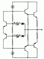
Attached is the circuit diagram - change the output transistors to GA10JT12-247, instead of our obsoleted GA03JT12-247.
Also attached is the PCB picture.
in the zip file are all the CAD/gerber files.
This is continued from thread " Semisouth goes Dodo ; what now ?"
Attached is the circuit diagram - change the output transistors to GA10JT12-247, instead of our obsoleted GA03JT12-247.
Also attached is the PCB picture.
in the zip file are all the CAD/gerber files.
Last edited by a moderator:
BTW, I can post the Class A design on the forum (have to figure out the attachments). Would that be of interest?
Now we're getting somewhere!
Hmm.. WalterW, why Class A? We already have a company design a Class A with our devices, and they were ecstatic about the response. But my EE knowledge suggests you can get better efficiency/power with Class AB, without sacrificing too much on linearity, if done properly...
Generally, ClassAB amps are biased very lightly for only very low ClassA output. The transition to ClassB causes a non linearity or crossover distortion in an important area to the listener. This can be avoided by running deeper ClassA or higher bias. If you want to look at this in terms of typical specs, at around the A-B transition the distortion will be high. Most mfg's would not give a measured number there due to the results. But, higher power may show better results. This usually causes distortion to be higher at lower power and lower at higher power. Not exactly good sounding.
Of coarse all of this can be changed with feedback. But, here in the Pass Labs forum, we try to get the most linearity possible with minimal or even no feedback, expecting to get better sound. ClassA makes this possible.
Last edited:
I was mistaken - the design in post#187 above is NOT a Class A design. It is a "dynamic biasing design" (I have no idea what that means). It is supposed to give a Class A performance (linearity) without the power dissipation of a Class A.
Anyway, it is a preliminary design only - should not stop you from coming up with your own pure/optimized Class A design.
I will try to edit my previous post #187 now.
Anyway, it is a preliminary design only - should not stop you from coming up with your own pure/optimized Class A design.
I will try to edit my previous post #187 now.
I don`t understand why you labeled pins GDS on the GA10JT12-247 datasheet when one could see it`s a NPN transistor??
There is no data below 5A on the DC current gain/"drain" current and that is important in audio applications and below 10A is going down...
How one could see from the datasheet it is very linear as you say?
Why there`s no Ft of the transistor?
etc...
example:
http://www.genesicsemi.com/images/products_sic/sjt/GA10JT12-247.pdf
And yes, btw Nelson do not use bipolar transistors in output stages for more then 20 years...
Last edited:
I don`t understand why you labeled pins GDS on the GA10JT12-247 datasheet when one could see it`s a NPN transistor??
There is no data below 5A on the DC current gain/"drain" current and that is important in audio applications and below 10A is going down...
How one could see from the datasheet it is very linear as you say?
Why there`s no Ft of the transistor?
etc...
example:
http://www.genesicsemi.com/images/products_sic/sjt/GA10JT12-247.pdf
And yes, btw Nelson do not use bipolar transistors in output stages for more then 20 years...
This device is quite unique - it cannot be classified in the traditional NPN structure, or like a FET. It switches like a FET (purely capacitive); but has current gain (which if you think about it a JFET also has a finite current gain). In terms of temperature dependence of on-state and switching characteristics, it is a FET-like behavior. The physics of operation is NOT bipolar, and that is why we do not refer to this device as a "bipolar" transistor. It is not just a marketing game - there are good reasons for this nomenclature that many "experts" did not understand.
Most of the customers for this device are power switching applications - they do not care about current gain at much below the rated current - so our Current Gain vs Current does not go below 5 A. Can you please explain more why low current gain behavior is important? So, we can add it in the future.
The I-V characteristics saturate with near-infinite output resistance, which no other SiC device does. It also shows a much more flat Current Gain vs Current characteristics than Si NPN transistors - that is why we call it linear.
Most power switching customers use it only to ~350kHz, which is much lower than Ft. But we will update the datasheet soon with this information, now that many industrial customers have expressed strong interest in this device for audio applications. If someone in the group makes this measurement, please share them with us.
Ignoring the last statement - it has nothing to do with making the discussion smart.
Most of the customers for this device are power switching applications - they do not care about current gain at much below the rated current - so our Current Gain vs Current does not go below 5 A. Can you please explain more why low current gain behavior is important? So, we can add it in the future.
.
Ok, now is "little" more clear. I guess it isn`t kind of hybrid part, mosfet with integrated driver or something like that?
If you look at some audio bjt devices like 2SC5200, you will see that DC Current Gain vs Ic is fairly linear from 10mA to about 4 Amps and that range is in use for audio applications, class AB or class A, so it would be good to have separate graph from say 10mA to 10A.
I was mistaken - the design in post#187 above is NOT a Class A design. It is a "dynamic biasing design" (I have no idea what that means). It is supposed to give a Class A performance (linearity) without the power dissipation of a Class A.
While related, it leans more toward the circuit that Cordell used in his amplifier.
Attached are the front page image of my 1976 patent, and the central portion
of the one you posted. There are similarities between both, but the central
intent of mine was continuous forward bias of the output stage, and Cordell's
was output stage error correction.
Attachments
Very nice.BTW, I built a "Zen" version of an amplifier using the GA10JT12 in a single-
stage single-ended Common-Source amplifier without feedback, and I will
be posting the results shortly.
You work like a machine.
BTW, I built a "Zen" version of an amplifier using the GA10JT12 in a single-
stage single-ended Common-Source amplifier without feedback, and I will
be posting the results shortly.
Sounds great! I just happen to have a zen sittings around looking for an update. 😀
A short article describing the Genesic GA10JT12 transistor in a Zen type
amplifier circuit has been posted in the FW articles section.
FIRST WATT
amplifier circuit has been posted in the FW articles section.
FIRST WATT
- Home
- Amplifiers
- Pass Labs
- Semisouth goes Dodo ; what now ?