The smarter greedy boyz would snap up a few R085's.

Going for ?$90/piece -- what is a reasonable price?
btw. what's price of SS enhancement ones , nowadays ?
I got some R100s at $24/piece.
Going for ?$90/piece -- what is a reasonable price?
Who's offering them for $90?
Going for ?$90/piece
I guess my purchase qualifies as an investment.
I guess my purchase qualifies as an investment.

You are a market maker
Of course it varies with bias and a little bit from device to device, but at VDS = 11.7 V and ID = 1.38 A and VGS = 1.575V, I have data for one SJEP120R100 where rds = 91 Ohm and gm = 10.8 S so mu = rds*gm = 983.
How the drek (thanks zen) can a power JFET with these specs get anywhere close to the operation of a real 6L6 Tube?
Are there characteristic curves of this modified R085 device you'd be willing to share?
I can guess there might be some serious source degeneration and/or VGS attenuation going on in there...
In the solid-state tube, we are not modifying the SJDP120R085 JFET so much as we are using it in an application. We use a 6L6 data sheet to determine the characteristic curves.
Surprised that one would want to emulate a 6l6.
My '64 Fender Bassman uses those tubes (AA864).
Works fine, has done since I bought it used, in early 70s.
Amazes me that someone would go to large efforts to replicate such
I mean it is good.. but it Ain't That good.
Most of it's popularity with Guitar people lies in it's Vintage (drifted resistors sound.
My '64 Fender Bassman uses those tubes (AA864).
Works fine, has done since I bought it used, in early 70s.
Amazes me that someone would go to large efforts to replicate such
I mean it is good.. but it Ain't That good.
Most of it's popularity with Guitar people lies in it's Vintage (drifted resistors
Trying to read between the lines, Papa told us he was testing these awhile ago and we haven't heard an encouraging review so I'm assuming not worth it?
Trying to read between the lines, Papa told us he was testing these awhile
ago and we haven't heard an encouraging review so I'm assuming not worth it?
I did test these, and I liked the UJN1208's particularly, and so far they appear
to be the best depletion mode power JFET I have, by a small margin.
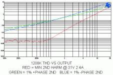
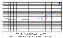
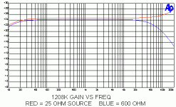
Here are some curves operated Common Source into 8 ohms, with Vds at 32V,
and 2.3A bias.
The distortion vs amplitude shows three bias settings, with +2nd harmonic,
-2nd harmonic, and suppressed 2nd (the lowest).
The distortion vs frequency is seen with low impedance vs high impedance
sources as are gain/frequency response.
Attachments
Here are some curves operated Common Source into 8 ohms, with Vds at 32V, and 2.3A bias.
I assume that means resistor-loaded and not CCS? Is that a single device or several in parallel?
In the solid-state tube, we are not modifying the SJDP120R085 JFET so much as we are using it in an application. We use a 6L6 data sheet to determine the characteristic curves.
Hello Dr. Mazzola.
Does your note above suggest the current designs with R085 continue to use the Bender's original power output transformer? Do you foresee a change to a different power output transformer which can manage a much higher current at reasonable Vds with R085?
...I liked the UJN1208's particularly, and so far they appear to be the best depletion mode power JFET I have...

Oh no... I just loaded up on R085's...

Oh no... I just loaded up on R085's...
Actually, I have one design where the R085's Vgs is a better fit.
- Status
- This old topic is closed. If you want to reopen this topic, contact a moderator using the "Report Post" button.
- Home
- Amplifiers
- Pass Labs
- SemiSouth boiler room


