Clueless.
You have to read a lot about how to make a very good PCB, immune to parasitic oscillation. You have to make the PCB material work for you not against you. More than that, you have to iterate many times in order to obtain a stable amplifier.
Are the locations of the base stoppers critical?
Gate stoppers require to be close to the FET, to minimise the resistor to gate inductance.
Yes, the stopper resistor location is critical and must be as close as possible to the transitsor base
You have to read a lot about how to make a very good PCB, immune to parasitic oscillation. You have to make the PCB material work for you not against you. More than that, you have to iterate many times in order to obtain a stable amplifier.
An emitter follower given an appropriate load (such as a high fT driver working into the input capacitance of a bunch of paralleled low-fT power output devices) can make a reliable oscillator regardless of the brilliance (or otherwise) of the PCB layout.
Dismissing any stabilisation technique (or theoretical discussion) beyond the basic application of base-stopper resistors with “The true art is to stabilise the circuit only by layout” is a nonsense.
I have never sed "no basestoper resistors" or "no decoupling-capacitors" are required, only a good PCB layout is required to to tame HF oscilations in EF stages!
Last edited:
That is the brute force approach! The true art is to stabilize the circuit only by layout.
Keep in mind that 10ohm in driver collectors drop 2V at 100mA, which is a headroom killer if you do not use separate driver PSU.
Hi Roender,
5 ohms in the collector of a 100 mA driver will drop only the 0.5V I recommended.
While I will always be the first to say that good layout is very important, to depend solely on layout for avoidance of parasitic oscillations is what I would call the brute force approach. We always want to strike a balance between the various techniques.
Cheers,
Bob
Are the locations of the base stoppers critical?
Gate stoppers require to be close to the FET, to minimise the resistor to gate inductance.
Base stoppers usually want to be right at the base. Stray trace capacitance on the base line outside the package will tend to defeat some of the action of the base stopper.
Cheers,
Bob
You have to read a lot about how to make a very good PCB, immune to parasitic oscillation. You have to make the PCB material work for you not against you. More than that, you have to iterate many times in order to obtain a stable amplifier.
If you have to iterate many times the layout to obtain a stable amplifier, then the circuit is hopelessly sensitive to layout. Not a good approach.
We want margin. I suspect that there are many amplifiers out there where the designers struggled with the layout or whatever to stop parasitics, but had no idea how close the amplifier was to the edge, especially under different operating and load conditions. These amps can have bursts of oscillation in service that may account for poor sound that is not revealed by conventional bench testing.
Cheers,
Bob
Hi Roender,
5 ohms in the collector of a 100 mA driver will drop only the 0.5V I recommended.
While I will always be the first to say that good layout is very important, to depend solely on layout for avoidance of parasitic oscillations is what I would call the brute force approach. We always want to strike a balance between the various techniques.
Cheers,
Bob
I'll always prefer only base stoppers and collector decoupling capacitors. A good layout do not require anything else beyond this.
I have never sed "no basestoper resistors" or "no decoupling-capacitors" are required, only a good PCB layout is required to to tame HF oscilations in EF stages!
Whatever. Time to tune out of this thread.
We want margin. I suspect that there are many amplifiers out there where the designers struggled with the layout or whatever to stop parasitics ...
Bob
I'm sorry to say that, but IMHO to much margin kill the sound.
That is the brute force approach! The true art is to stabilize the circuit only by layout.
Keep in mind that 10ohm in driver collectors drop 2V at 100mA, which is a headroom killer if you do not use separate driver PSU.
Yes you are correct, base-stopper also increases the distortion principally the output TRs. Besides a good design of the pcb, is necessary to take care not to use a resistor reactive ,inductive or capacitive,the correct is use of metal-film.
Attachments
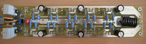
Very good!!!Thanks for that one. I tried the inductors in my quest to turn my OPS into a Colpit's oscillator , success !!Adding that resistance absolutely stopped it , even with 100's of nH's on bases/collectors ,just small a burst of damped lower freq osc.... and with the 20nH .. nothing.
So with basestoppers everywhere , current sourced drivers , and those "magic" 10R driver collector resistors , this might "fly". Here is the "close" version (attachment) Another plus is the THD 20 dropped a little more (.002% @ 300w/2R
OS
My simulation "traditional" Locanthi T circuit
Attachments
I'm sorry to say that, but IMHO to much margin kill the sound.
Roender,
Bear in mind, I am not advocating a significant reduction in bandwidth. If it is done right, there will be little reduction in speed.
If there is a different reason why you assert that the use of these techniques impairs the sound, please elaborate on your reasons.
Cheers,
Bob
Guys,
Have you ever heard about gyration theory in EF stages, where in some operating conditions every base resistance gyrate into emitter inductance? I will search trough my archive for that document...
Cheers,
Mihai
Yes, I am very familiar with it, and you are correct. We always need to do the math and take these effects into account.
Bob
One more point that is important in regard to the use of base stopper resistors. Their use does tend to decrease thermal bias stability. This is due to the voltage drop across them that results from base current. The base stopper should usually be sized so that this voltage drop is less than 10 mV with the lowest beta expected. Less than 5 mV is even more desirable.
An output transistor biased at a current of 100 mA and with a beta of 50 will have 2 mA base current. A 5-ohm base stopper will drop 10 mV.
Cheers,
Bob
An output transistor biased at a current of 100 mA and with a beta of 50 will have 2 mA base current. A 5-ohm base stopper will drop 10 mV.
Cheers,
Bob
- Status
- This old topic is closed. If you want to reopen this topic, contact a moderator using the "Report Post" button.
- Home
- Amplifiers
- Solid State
- Self type 3 EF (hybrid triple)... any pointers ??