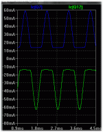
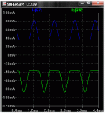
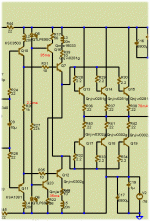
You decide ,raphael... play with this (attached zip).
models are included in .asc .
OS
Thanks, the current consumed by the pre-driver is very good (~25uA for 2R load), that reduced the distortion in the VAS .The driver really are in class AB, the output stage requires 50mA/4R and 100mA/2R, to polarize in class A, you need greater Bias than required by Ib in output TRs.
-I do not know if have problem has topology opposite rails, be conducted in class AB ( I think not!!)
Bob,
I don`t have anything to add.
It`s a pity that linear complementary driver-MOSFETs are not easily and cheaply available (like the 2SK213/2SJ76 family, Crss just 2.2pF/4.8pF), offering infinite input impedance over a wide frequency range and a small gate-source threshold voltage.
I don`t have anything to add.
It`s a pity that linear complementary driver-MOSFETs are not easily and cheaply available (like the 2SK213/2SJ76 family, Crss just 2.2pF/4.8pF), offering infinite input impedance over a wide frequency range and a small gate-source threshold voltage.
I am using a triple on my amp (Locathi T) and have the pre-drivers and the drivers running in class A (120mA). Across the driver base to base spreader resistor I have a 1uF stacked foil for charge suckout. I run each output transistor pair at c. 115ma bias (0.22Ohms and the 25mV thing). This is a big amp, so running the drivers in type III mode by returning the emiitters to th e rails through resistors or CCS is not a good option. I am currently using 21193/21194 pairs. One thing I really struggled with on this amp was HF oscillation in th e output stage. Eventually, I had to insert a 27 Ohm resistor in series with each driver base, and then directly from the base of each driver to ground a 1nF cap. I tried everything to ommit this network but to no avail. I efven got hold of an app note from microcap which gave a model for this type of oscillation and it pretty much ties up with what I found (and the solution is the same one I ended up using). However, I see loads of circuits using triples and no use of any networks (other than vbase stoppers). Any ideas on whats going on here? BTW, the board layout is quite compact, so I doubt it is a layout issue.

BTW, the board layout is quite compact, so I doubt it is a layout issue.

It is a layout issue ... a big part of the problem!
I was able to get this run stable, CFP drivers loaded by CCSs from opposite rail, and it sound very very good! The only downside is the complexity and the thermal dissipation from drivers and CCSs, because you need at least 100mA through each driver to run stable!
From my POV, this is the almost perfect class B output stage, as per Self OPS class definition.
Is this in a triple or just a EF ?? Ive used cfp predrivers with BJT outputs in a triple and its very unstable, mosfet outputs, no problems.
Bonsai, have to agree with Roender, layout is vital here, Ive had to redo my board 6 times before having one working perfectly, also its quite important using the lowest Cob predrivers one can find.
... also its quite important using the lowest Cob predrivers one can find.
That's true and more than that, the slave BJT in CFP compound must be biased at around 75% driver Ft.
All the tests I've done were with CFP drivers, CCS biased from opposite rail and BJT outputs. From my POV, the complexity and thermal dissipation dose not justify the sound enhancement over simple CFP drivers as I used in my RMI-FC100
By bonsai - One thing I really struggled with on this amp was HF oscillation in the output stage.
It is good to see someone who uses the 21193/4 pair .. MJ - MJL - or NJW ?? "trouble with triples" is the D. self dissertation on this subject and the reason i am listening to a double EF and not a triple now.
As one just beginning to understand the pole/zero concept , adding another pole (the predrivers) , is what puts the type2 "over the edge". In my one attempt (prototype) , I added 100pf mica's from each main driver base to their rails. Before doing this I would get thermal runaway/biasing issues (hot drivers).
What is funny , LT showed this parasitic oscillation when using new models (KSA/mje/njw - fairchild and on- semi) ,which at least gave me some hint at a possible solution. 2 things triggered the oscillation , heavy xover glitches (underbiased OPS) or a amp with very high OLG (80db+ - self amp /w CM).
On this type 3 , I am amazed to see no such oscillation - but this could be because I am running it with my sub 70db OLG symasym voltage amp.
so running the drivers in type III mode by returning the emiitters to th e rails through resistors or CCS is not a good option
There is no difference , the standard "T" just forms a crude current source between driver emitters (as mr. Cordell pointed out) while this variant just "locks" this current with an active CCS referenced from the opposite rail. Both run fully in class A . If you look at the total Ic on each driver , the 2 and 3 are in the same ballpark dissipation wise. (attachment 1 is "leach" triple , 2 is the type 3 variant). with outputs as the main driver pair , the combined Ib of of the outputs + the class A bias current (simple resistor vs. the CCS's) , the same thing !!
I see loads of circuits using triples and no use of any networks (other than vbase stoppers). Any ideas on whats going on here? BTW, the board layout is quite compact, so I doubt it is a layout issue.
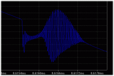
" Too much current gain" .... I actually tried to get simulated oscillation with my simulated circuit. (attachment 3) I used the standard "T" with the ksa's as predrivers , 2sa1837/2sc4793 drivers (high beta) , and NJW0281/0302 as OP's. I got it .. at 1.2mhz , at the xover point , even with the super stable symasym voltage amp.
OS
Attachments
Last edited:
The inductor in the output should resolve the oscillation, you must maintain good phase margin (>70°).One thing I really struggled with on this amp was HF oscillation in th e output stage. Eventually, I had to insert a 27 Ohm resistor in series with each driver base, and then directly from the base of each driver to ground a 1nF cap. I tried everything to ommit this network but to no avail. I efven got hold of an app note from microcap which gave a model for this type of oscillation and it pretty much ties up with what I found (and the solution is the same one I ended up using). However, I see loads of circuits using triples and no use of any networks (other than vbase stoppers). Any ideas on whats going on here? BTW, the board layout is quite compact, so I doubt it is a layout issue.

See example of Leach amp.
Your problem may be bias with duplication GM, your bias is quite high...
Lumba,
Bear in mind that this type of Triple is just a variant of the legendary Locanthi T circuit which has withstood the test of time for over 40 years. The most important aspect is the fact that it is a Triple and posesses plenty of current gain to isolate the load from the VAS. A simple Darlington does not have enough current gain to adequately isolate the load from the VAS, especially when low-Z loads are being driven. The other nice thing about the Locathi T circuit is that the emitter followers are largely loaded by curreny sources formed by the relatively fixed bias spread between the emitters and the emitter-emitter resistors. To the extent that this bias spread changes with signal conditions, the current source formed by this approach is imperfect. In any case, the extra BE junctions in the signal path do not add substantially to the nonlinearity.
A related and significant advantage of the Locanthi T circuit is that the pre-drivers and drivers run in class A.
It is very important that in any of these arrangements, adequate turn-off standing current be set up in the drivers to suck carriers out of the output transistors when there is a high rate of output current change (Amps/us).
It is interesting that up until about the Fourth edition, Self hardly even mentioned the Locanthi version of the Triple. Guess he finally got religion.
Cheers,
Bob
What about a simple Emitter Follower buffering the VAS ?
Both D.Self (insertion of a boostraping EF, adding just one transistor and one resistor to the VAS) and Cherry (insertion of a complete buffer stage made of an EF loaded by a CCS) are in favour of such a buffer which garantees a more stable bias voltage than a class A push-pull EF driver.
However I have almost never seen this solution used and wonder if it is worth to include in a standard amplifier.
Strange that you mention it doesnt get used, Self used it in the cambridge range amps if I remember correctly, I think the amp in question is the Azur 640, a soon as I get home Ill post some more commercial designs using that exact method. Another example is an old amp made by founder of HP, Barney Oliver, here on the forum Dr Jgodic has used it to good effect.
I am using a triple on my amp (Locathi T) and have the pre-drivers and the drivers running in class A (120mA). Across the driver base to base spreader resistor I have a 1uF stacked foil for charge suckout. I run each output transistor pair at c. 115ma bias (0.22Ohms and the 25mV thing). This is a big amp, so running the drivers in type III mode by returning the emiitters to th e rails through resistors or CCS is not a good option. I am currently using 21193/21194 pairs. One thing I really struggled with on this amp was HF oscillation in th e output stage. Eventually, I had to insert a 27 Ohm resistor in series with each driver base, and then directly from the base of each driver to ground a 1nF cap. I tried everything to ommit this network but to no avail. I efven got hold of an app note from microcap which gave a model for this type of oscillation and it pretty much ties up with what I found (and the solution is the same one I ended up using). However, I see loads of circuits using triples and no use of any networks (other than vbase stoppers). Any ideas on whats going on here? BTW, the board layout is quite compact, so I doubt it is a layout issue.

Hi Bonsai,
Triples are wonderful in many ways, but at times they can be hard to stabilize. We all know that a single emitter follower can sometimes like to oscillate, so having a string of three adds to the possibilities. The key is to try to kill the parasitic oscillations without killing most of the bandwidth of the circuit.
My usual understanding of the problem is two-fold. First, we know that EFs get to have a negative input impedance when they see a load capacitance. The usual fix for this is to put in a base stopper resistor OR to put a resistance in series with the emitter before it encounters the load capacitance.
In a Triple, a base stopper resistor between the stages essentially accomplishes both. So, for example, a couple ohms base stopper in each output transistor isolates the driver from the load and base-collector capacitance of the output transistor. A few tens of ohms in the base of the driver isolates the pre-driver from the base-collector capacitance of the driver and any negative resistance at its base. Even 100 ohms is not bad to put in the base of the pre-driver to isolate it from the VAS. These low values of resistance will usually not seriously compromise the bandwidth of the stage (no shunt capacitors added).
The second piece has to do largely with the base-collector capacitance and stray inductance, often in the collector. If there is 10-20 nH in the collector and Cbc is 100 pF, we can have a resonant circuit in the tens of MHz. This can cause trouble. In other words, it is not always just negative resistance from EFs that is the cause of the problem; we can form oscillator topologies. I explained this a bit in my MOSFET EC amp paper in connection with taming MOSFETs. Its not too hard to form a Hartley or Colpitts oscillator with a little bit of inductance.
What we want to do here is to damp out the Q of the inductor so that the resonant circuit that is formed isn't very "good". Here, some resistance in the collector can help. If you can afford it, maybe drop a half volt of DC across a resistor in the collector. Ten ohms in the collector of a driver running 50 mA would do it.
It is a good idea to simulate Triples with 20 nH of inductance in one or more of each transistor's leads to bring the simulation more into the real world. Don't forget that there is still bond wire inductance inside the transistor even if the outside latyout is perfect.
The key here is to recognize that it is a layout probem (inductance in the collector, for example), BUT we want to design the circuit so that it is more robust in the presence of imperfect layouts.
Finally, note that people often kill oscillations with ferrite beads. They are frowned upon in audio, but I bring them up to point out that what they are usually doing is killing the Q of a resonant circuit at high frequencies without incurring any DC voltage drop. A feerite bead becomes resistive, usually 10-100 ohms, at high frequencies, killing Q.
One last thing. Another useful approach is to employ Zobel networks (series R-C) in parallel in some places; once again, the resistance they show at high frequencies kills Q. One technique I use to tame MOSFETs is to put something like 100 pF in series with 100 ohms from gate to ground or, sometimes even better, from gate to drain (even though the drain is technically at AC ground).
Cheers,
Bob
It is good to see someone who uses the 21193/4 pair .. MJ - MJL - or NJW ?? "trouble with triples" is the D. self dissertation on this subject and the reason i am listening to a double EF and not a triple now.
OS
Hi OS,
I am unfamiliar with the D Self dissertation on trouble with Triples. Is it available somewhere?
Thanks,
Bob
Hi OS,
I am unfamiliar with the D Self dissertation on trouble with Triples. Is it available somewhere?
Thanks,
Bob
I believe it is the title of an article by Doug in WW (or EW). I'll see if I can chase it up.
jd
I believe it is the title of an article by Doug in WW (or EW). I'll see if I can chase it up.
jd
Hi Jan,
Thanks!
Will you be at RMAF? If so, I'll look forward to seeing you there.
Cheers,
Bob
By Bob Cordell - Hi OS,
I am unfamiliar with the D Self dissertation on trouble with Triples. Is it available somewhere?
http://books.google.com/books?id=EChweaOYqbMC&pg=PA132&lpg=PA132&dq=trouble+with+triples&source=bl&ots=DtMPU0K8YK&sig=xKPxY_fm1R4lt-0HyQLVv_dVfEY&hl=en&ei=vbuUSqPLAYGRtgek7IxK&sa=X&oi=book_result&ct=result&resnum=6#v=onepage&q=trouble%20with%20triples&f=false
In the hand book , page 132 , he continues his triple discussion to P 139.
After reading that , and his spice experiences , namely "gain wobble".. I decided to try to get my triple to match a known EF in that regard. the "wobble" definitely increases with pre driver/driver beta . Even with my low beta NJW's a main drivers , only 25uA is required for a 2R load. good enough..
In a Triple, a base stopper resistor between the stages essentially accomplishes both. So, for example, a couple ohms base stopper in each output transistor isolates the driver from the load and base-collector capacitance of the output transistor. A few tens of ohms in the base of the driver isolates the pre-driver from the base-collector capacitance of the driver and any negative resistance at its base. Even 100 ohms is not bad to put in the base of the pre-driver to isolate it from the VAS. These low values of resistance will usually not seriously compromise the bandwidth of the stage (no shunt capacitors added).
So use basestoppers everywhere .. resistors are cheap ...
One last thing. Another useful approach is to employ Zobel networks (series R-C) in parallel in some places; once again, the resistance they show at high frequencies kills Q.
I've seen this on many japanese triples .. A R-C in parallel with a small inductor between pre and main drivers , usually when the OP's are offboard (wires - TO3 )
OS
By Bob Cordell - Here, some resistance in the collector can help. If you can afford it, maybe drop a half volt of DC across a resistor in the collector. Ten ohms in the collector of a driver running 50 mA would do it.
Thanks for that one. I tried the inductors in my quest to turn my OPS into a Colpit's oscillator , success !!
So with basestoppers everywhere , current sourced drivers , and those "magic" 10R driver collector resistors , this might "fly". Here is the "close" version (attachment) Another plus is the THD 20 dropped a little more (.002% @ 300w/2R
OS
Attachments
Last edited:
Adding that resistance absolutely stopped it , even with 100's of nH's on bases/collectors ,just small a burst of damped lower freq osc.... and with the 20nH .. nothing.
So with basestoppers everywhere , current sourced drivers , and those "magic" 10R driver collector resistors , this might "fly".
OS
That is the brute force approach! The true art is to stabilize the circuit only by layout.
Keep in mind that 10ohm in driver collectors drop 2V at 100mA, which is a headroom killer if you do not use separate driver PSU.
Strange that you mention it doesnt get used, Self used it in the cambridge range amps if I remember correctly, I think the amp in question is the Azur 640, a soon as I get home Ill post some more commercial designs using that exact method. Another example is an old amp made by founder of HP, Barney Oliver, here on the forum Dr Jgodic has used it to good effect.
I'll see these commercial designs with great pleasure.
Thanks in advance.
Barny Oliver's amp :
An externally hosted image should be here but it was not working when we last tested it.
Last edited:
- Status
- This old topic is closed. If you want to reopen this topic, contact a moderator using the "Report Post" button.
- Home
- Amplifiers
- Solid State
- Self type 3 EF (hybrid triple)... any pointers ??


