By roender - If I were you, I would try to decrease R27 and R31 to 1ohm and put 1uF from driver collector to ground
please explain ?? Those 2- 6.8R resistors do increase the "margin" against oscillation(as B. Cordell explained). They also cause a .1v drop from the rails to driver collector(not too much). The caps you mentioned ,
 what are their purpose ??
OS
by roender - You would need more than 15mA trough drivers in order to have a good sounding amplifier ... I would say at least 100mA
Do the math again, for voltage drop over thous resistors, and tell me if you'd accept such headroom lost
Sorry , that OPS I just posted was my "jury rigged" triple to see if I would get a
 ...that one has KSA/mje/njw , and only 14-16ma bias on the drivers.
The final version will be this .. (attachment 1) , it will have trimmable CCS's (r50/51) , allowing for adjustment between 20-100mA . At 26mA , nothing switches off (attachment 2) simmed at 2-8R. If you say the best sound is with the higher bias , that will be just a twist of the screwdriver away. (attachment 3) is the voltage drop across R27/31 at 26mA. At higher driver currents , I agree the drop would be excessive , especially with a 2R load!!
OS
Attachments
Last edited:
ostripper ,
congratulations, this is the very best triple Darlington implementation so far, carefully chosen resistor values.
congratulations, this is the very best triple Darlington implementation so far, carefully chosen resistor values.
No doubt about it, you could go for the highest reasonable level right away, using fixed resistors.If you say the best sound is with the higher bias
By LO - congratulations, this is the very best triple Darlington implementation so far, carefully chosen resistor values.
Thanks, by the fact that the simpler "T" version of it is still not malfunctioning , this conceptual version "T3T" will at least work , maybe even give me the H3/5/7 free result like the FFT (attachment 1).
Just a "sneak peek" at the full package (as it will be built - attachment 2).
Roender is right , the 6.8R driver collector resistors would be better as 1-2R (better for difficult loads).
PS .. on the fft I stepped 2/4/6/8R.... remains the same. Distortion and FFT also stays nearly the same at 10 or 20k !!
OS
Attachments
Last edited:
By aska - you don't need the 10R base stoppers on the drivers. They never turn off.....
While nothing goes crazy without them 10R's (you are right) , I did notice while turning this triple (the whole amp)into a oscillator (too much OLG , not enough Cdom , highest Hfe in OPS) ,the addition of any low value basestopper to the driver (you notice it is an output) further damped the ringing that I was purposely creating (increasing the margin).
The simulations tell the story... (attachment1) is with ..and (attachment2) without.
Harmon Kardon , the apt , nakamitchi all use the stoppers between pre/driver.
To be fair , I tried a lower Cob driver 2sa1837/2sc4793 ...same "effect" , but at lower Cdom . "cause and effect" seems to point to the Cob of the driver.
PS - the amp "choked" at 20p/ no basestopper. With the basestopper I could still simulate at 10p (2mhz UGP !!).
OS
OS
Attachments
Last edited:
I think the stoppers on th e driver (and pre-driver in the case of a classic T Triple) are important event though the drivers do not turn off, or only turn off in case of very heavy drive. I got similar results to Ostripper on simulation and in practice on the classic T tripple. As discussed a few posts ago with Bob Coredell, I ommited base stoppers on the output device bases - this was a mistake on my part that I am rectifying. The only way I cured it was with the 1nF/27 ohm network on the bases of the drivers - but this creates a pole that causes its own set of problems.
The problem of this topology VAS balanced, is what use two outputs of the differential pair. The bias in the vas balanced is different in the two transistors, this creates a different roll-off the differential pair. for exemple, roll-off begins 6 dB/8° then changes to 20dB/Dec and then returns to 6 dB/8° the circuit is unstable at high frequency even if the phase margin is <180°, many will find the problem is local oscillation in the output stage, but really not is...
By rafael luc - The problem of this topology VAS balanced
I tried that , using a standard CCS'ed VAS (self amp) , I did the same test (destabilizing the amp) and look !! (attachment 1) . The self amp broke out in sustained oscillation , same T3T triple OPS - same cascoded input stage. At 100mA OPS bias and a normal Cdom all was the same (.003% THD20- It ran good).
the bootstrap VAS will also do sustained oscillation (tried that ,too) Where you are correct is the differences in slope of the 2 "halves" of the balanced VAS. But , that .001u cap I use at the "backend" and the current mirror take care of that.
So if it is a "problem" to have a more stable amp with more "margin" ..
also , besides the real one i have now , the simulations do not support this. 
OS
Attachments
Hi ostripper
You should see the two Roll-Off (loop-DC) in outputs of the differential pair, if not is equal, may be unstable. I tried the VAS balanced of book Self and I did not like, Self also deals briefly this topology...
For example, Symasym is unstable at high frequency due to different roll-off. The solution was to reduce the Slew-Rate to make it stable (20V/us)
I tried several attempts, the better it seemed to me that here:
http://www.diyaudio.com/forums/showthread.php?t=145798&highlight=SuperSymasym&page=18
Slew-Rate is 90Vus
- I Not tried with current mirror
Roll-Off Supersym2:
Attachments
This is an example of oscillation, the phase margin this OK (~80°), this was the problem I had:
http://www.diyaudio.com/forums/attachment.php?attachmentid=131668&d=1240002821
http://www.diyaudio.com/forums/attachment.php?attachmentid=131668&d=1240002821
Symasym is unstable at high frequency due to different roll-off.
That is the reason for the "supersym" and this T3T OPS. I found this paper , it is for testing the stability of op-amp's , but will carry over to a "big amp".
http://www.analogzone.com/acqt1211.pdf
At 2uF , no problem , same with 6uf , but at a full 10uF ...this (attachment 1) is what happens. This is more than the OPS would probably ever see , even with electrostatics. This particular topology seems to negotiate this test the best , even at 60+ V/uS slew.
OS
Attachments
OS how do these amps sound compared to the genesis stealth?
By the way... can you pm or email me your new phone number and email address?
I've been trying to get ahold of you about finishing my Stealth amp repairs. I haven't heard from you in a couple months about the progress. I'm getting a little nervous.
By the way... can you pm or email me your new phone number and email address?
I've been trying to get ahold of you about finishing my Stealth amp repairs. I haven't heard from you in a couple months about the progress. I'm getting a little nervous.
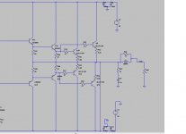
hi . this is my output stage should i put base stopper resistors at the base of the drivers as well as 2 ohm collector resistors, and base stopper resistors at the base of the predrivers for better stability?
when i put 20nH coils at the collectors of the drivers i get a peak at the closed loop response at frequences very far away from transistors ft .is it warning for the reality design?
when i put 20nH coils at the collectors of the drivers i get a peak at the closed loop response at frequences very far away from transistors ft .is it warning for the reality design?
Attachments
hi . this is my output stage should i put base stopper resistors at the base of the drivers as well as 2 ohm collector resistors, and base stopper resistors at the base of the predrivers for better stability?
when i put 20nH coils at the collectors of the drivers i get a peak at the closed loop response at frequences very far away from transistors ft .is it warning for the reality design?
10-22R base stopper - Q14/16
2.2R - 10R collectors - Q14/16
100R base stopper - q12/19
You biased q12/19 with 68R , lowering the current gain of the triple , while this will increase stability , it goes against the whole purpose of a triple EF ,(minimum load on the VAS / VERY high GM).
OS
thank you.i will put these resistors.
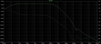
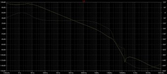
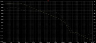
I have another questions.these are 2 loop gain (not closed loop gain) curves of the same amplifier using different values for lead and compensation capacitors.The output transistors are TOSHIBA 2sc5200-2sa1943 with a Ft of 30Mhz.
LTspice shows that there is a gain peak at a frequency of above 100Mhz.
should i ignore this because of its being at a frequency very higher than the transistors Ft or should i always aim for the curve to be a falling straight line with no peaks even at higher frequences than the Ft of the used transistor??
Attachments
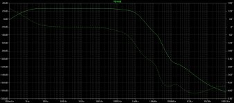
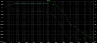
...and these are the closed loop gain curves that correspond to the previous loop gain curves. which one is better? i think the second one because the curve is more smooth.
Attachments
Last edited:
- Status
- This old topic is closed. If you want to reopen this topic, contact a moderator using the "Report Post" button.
- Home
- Amplifiers
- Solid State
- Self type 3 EF (hybrid triple)... any pointers ??