Hey guys,
I've been playing around with the NEC cdrom as well and I've identified most of the chips:
CXA1610M > RF amp for laser control
TA8407F > Dual op amp, don't know purpose
NEC7225G > LCD controller for front display
D2559Q > 1 bit DAC, most undoubtably for headphone jack, although not sure if it's signal goes to the back audio output
CXD1808AQ > Sony CD rom decoder chip
CXAB72AQ > Sony RF processing chip, focus, mirror, those kinds of things
53CF92A > SCSI interface chip
BH9595FP > SCSI terminator chip
NN514256J-45 > Ram
I've actually done some surgery on mine, in an effort to try to understand it more. I've removed some of the chips sucessfully while still having the unit perform for audio. Those chips are the ram and associated resistor packs, scsi terminator, scsi interface. Removing the cdrom decoder chip causes the unit to not work, as well as the socketed dip (bios most likely)
I don't understand why removing the decoder causes the unit to fail, when the big sony 2510 chip should be the one responsible for audio. The ram interfaces to the the 1808 chip, but it doesn't seem to mind the removal of the memory (for audio only of course)
You might be asking why I'm going through the trouble of removing components. First, I'm trying to understand the thing, and second, I'd like to cut down on as much additional noise as possible. Can't hurt right?
I did locate the data xfer lines from the 2510 chip to the D/A. I don't excatly recall right now the pins right now, but i'll look it up later for anyone interested. I found bit clock, serial data, and word clock. Are these the lines people are hoping to tap for a outboard D/A? In addition to going to the DAC, the three lines also go to the 1808 cd rom decoder. I don't know the path these lines take to become ttl or spdif.
Any one know if the 3 lines from the 2510 can drive most a TDA1543 directly? or would a TDA1543A be needed?
cheers,
Norman

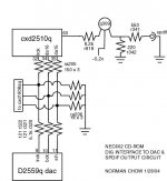
Here's what I've mapped out as far as the digital interfaces and spdif so far. Thought it might help some of you out.
I'm confused as to R341, labeled 195 (190k) but measures .5k.
So, all you digital gurus out there, what would be the best way to tap the EIAJ given this schematic and possible removal of the onboard dac? and why does the serial in resistor for pin 11 of the dac have a different value than the other two?
Norman
Attachments

Norman:
I like your schematic drawing.
Is Q309 on the digital out a transistor? If so, what
is its type (generic ID number).
Also, I notice that there are 2 black ground wires
going into the main ckt. board of the NEC. Are these
wires going to the same ground point on the board,
or are the +5 and +12 VDC grounds seperated on the
main board?
Thanks!
Fastcat
fastcat,
Q309 is marked BR 1. Does this sound right? I'm unfamiliar with surface mount transistor markings. I do believe its there to buffer or amplify the dig out.
The two black wires are internally tied together right where the connector enters the drive. They are one and the same.
So far, I've found the drive uses 12v, 5v, both of which are direct from the connector. Also, there's a 78M05A regulator internal which regulates the 12v down to 5.8v or so to power some of the chips.
Norman
Guys, if you want to save yourself the cost of a 8412, then do not use SPDIF. Just connect the LRCLK, DATA and SIN to the TDA1543A directly and it will work. If you want to use I2S, then build a format converter. The CXD2510 output EIAJ format. It is simple to convert from EIAJ to I2S with two chips. See schematic in other posts from me.
CM,
totally agree with you. I just recently got running a TDA1543A chip, directly wired via cat 5 to the three data and clock lines coming from the 2510 chip. No glue logic required! Although the dac is built with what components I had lying around (read: not optimized) the NEC 602/TDA1543 already sounds more detailed with more of a sense of space than my main cd player, a Rega Planet. Overall, the Rega still sounds slightly more musical and sounds less hard than the TDA1543, but a comparison of the two makes me suspect the Planet colors the sound and emphasizes the midrange. I think that with some work and careful component selection the TDA will blow the Planet away. I never knew how much detail i was missing with the planet. I'll post pics of my complete setup soon!
totally agree with you. I just recently got running a TDA1543A chip, directly wired via cat 5 to the three data and clock lines coming from the 2510 chip. No glue logic required! Although the dac is built with what components I had lying around (read: not optimized) the NEC 602/TDA1543 already sounds more detailed with more of a sense of space than my main cd player, a Rega Planet. Overall, the Rega still sounds slightly more musical and sounds less hard than the TDA1543, but a comparison of the two makes me suspect the Planet colors the sound and emphasizes the midrange. I think that with some work and careful component selection the TDA will blow the Planet away. I never knew how much detail i was missing with the planet. I'll post pics of my complete setup soon!

Schematics from NEC!
Hi,
good news from NEC. I have requested schematics for the external SCSI drive - and guess what, I got it!
After giving them an additional call I am now even allowed to share/post the schematics - but I have to state that there is no support and no liability of NEC for the correctness of these plans.
I will get out my old scanner during the weekend and make scans of the schematics. Should I post them here or can somebody provide some external webspace - IIRC there are 10 pages?
Bye,
Christian
Excellent!!!!!
Hi Christian,
excellent work!!! If you need some webspace, I could fit the files. I'll need to know how big they will be, and check that I have the bandwidth available for downloads.
Thinking about it - If I hosted the files as big pix with thumbnails, then we could use "save target as".........
I'm sure I can fit 10 pages. Do you have Acrobat? Perhaps they could be saved as PDFs.
Cheers
Jon
Hi Christian,
excellent work!!!
If you need some webspace, I could fit the files. I'll need to know how big they will be, and check that I have the bandwidth available for downloads.Thinking about it - If I hosted the files as big pix with thumbnails, then we could use "save target as".........
I'm sure I can fit 10 pages. Do you have Acrobat? Perhaps they could be saved as PDFs.
Cheers
Jon
dear all.
i stepped into mod. this CD rom!
and i changed the crystal (2 pin 33.8m)to oscillator(4 pin 33.8688m, 20ppm)
i cannot find any decoupling capacitor beside the sony decode/audio chips, so i planing to add some large cap.
but the space is critical... i have only choose some small value e.caps....
it would be great if you can post the sch. here, or if you ccnnot find a host to store the file, just tell me the file size, and i try to put it in my website and for every one d/l.
thanks
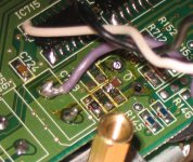
ps i will take some photo and share here
i stepped into mod. this CD rom!
and i changed the crystal (2 pin 33.8m)to oscillator(4 pin 33.8688m, 20ppm)
i cannot find any decoupling capacitor beside the sony decode/audio chips, so i planing to add some large cap.
but the space is critical... i have only choose some small value e.caps....
it would be great if you can post the sch. here, or if you ccnnot find a host to store the file, just tell me the file size, and i try to put it in my website and for every one d/l.
thanks
ps i will take some photo and share here
I'd loove to see the schematics! I tried to trace some of the board and did it sucessfully for power, but its tough to do! Please email me to my private mail if you can't post
BTW, looking to build an analog PS instead of a switching one for the drive, has anyone out there done so? Results? If anyone knows the amp requirements for both the +12 and +5 volt that would be cool =)
BTW, looking to build an analog PS instead of a switching one for the drive, has anyone out there done so? Results? If anyone knows the amp requirements for both the +12 and +5 volt that would be cool =)
Smoking scanner...
Aaargh!!!
Smoke comes out of my scanner - I cannot belive it. Never used the damn thing, wanted to sell it on ebay for months and now its broken.
Some resistor was burned, and my replacement has faced the same death - so thats only the symptom.
Sorry, but this has to wait at least until monday - I will use the scanner at work.
Christian
Takashi:
Can you tell me more about your changing the
crystal (2 pin 33.8m) to oscillator (4 pin 33.8688m, 20ppm)
as you mentioned in the post? I assume that the replacement unit is a low PPM crystal? Can you give me details as to where you obtained the replacement crystal, and its specs?
Also, I remember a post at another web site that said that the NEC 602 had 3 crystals on the main circuit board. I do hope that the full set of schematics get posted!
Fastcat
- Status
- This old topic is closed. If you want to reopen this topic, contact a moderator using the "Report Post" button.
- Home
- Source & Line
- Digital Source
- Schematics for NEC 602 CDROM Drive?