Hi Marra
I have to agree with Salas that it is a bit of a bodge, but it would certainly work (is RTV sealant like Araldite?). I understand that it is a hassle drilling the 4 holes and fiddling with the bolts. I used self locking nuts and M3 allen socket screws.
You could cut some metal / alumimium plates and glue the transformer to them and then bolt the plates to the chassis.
Thanks for the responses guys. The stuff I was going to use is Plumbers Gold actually a silicone sealant which I thought would hold things in place and provide some degree of vibration isolation. After thinking about it I will either bolt it down with some thin rubber between transformer and chassis or use rubber grommets and isolate it that way.
I'm thinking of using a modular approach using Hammond enclosures with p/s and optivol v/c in separate boxes feeding the DCB1 and p/s in separate boxes .
Any thoughts ? or am I just introducing to may interconnects.
I'm thinking of using a modular approach using Hammond enclosures with p/s and optivol v/c in separate boxes feeding the DCB1 and p/s in separate boxes .
Any thoughts ? or am I just introducing to may interconnects.
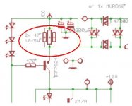
Those resistors will set the current that flows trough the regulator. The smaller they are, the more current will flow and the hotter everything will get, including the resistors themselves.
2x47 is the default, low-current version of the schematic, anything lower you put will result in more current. If you look trough this thread and/or the original build thread, you'll see many examples.
2x47 is the default, low-current version of the schematic, anything lower you put will result in more current. If you look trough this thread and/or the original build thread, you'll see many examples.
estimate the voltage across the current setting resistors.
As a first guess take 1.8V
The current through one 47r resistor is given by:
Iccs = V / R = 1.8 / 47 = 0.00383A = 38.3mA
Put in two parallel 47r and the total ccs current would be 2 * 38.3mA.
But before you decide to put in parallel resistors, build the circuit and measure the actual voltage across the current setting resistor. It could be anywhere in the range 1.4V to 2.2V and varies with the tolerances on all the components around the CCS.
Let's say you measure 1.681Vdc.
The CCS current is 1.681/47 +-resistor tolerance +-DVM tolerance. ~35.8mA+-tolerances
The power dissipated by that resistor is given by:
Pq = V^2 / R = 1.681^2 / 47 = 60mW.
A 600mW resistor will be running at ~ 10% of power rating (=cool).
Now add a second parallel resistor.
The voltage across the two resistors will drop slightly, maybe to 1.676V
The CCS current is now 2*1.676/47= 71.3mA+-tolerances and each resistor dissipates 59.8mW+-tolerances.
47r does not need to be a power resistor.
20r would dissipate ~150mW, a 250mW resistor would run very hot, a 500mW resistor will run just under hot, a 600mW resistor will run more than warm. You still don't need power resistors. But it depends on the voltage across the resistors. You must measure your build to find the Vdrop.
If you reduce the CCS current setting resistor to 10r then Pq does become an issue.
Do the measurements and do the sums.
Last edited:
I use clear window seal grade for building engines and gearboxes. It seems to perform better than Auto/engine grade.
It is a good adhesive. It is fuel and oil and pressure and water proof.
The only gasket I use is the head gasket and Wills rings, if any.
Never changed an exhaust manifold then, Andrew? Window sealant wouldn't cut it.
I don't but I was surprised when I opened up an engine for 6monthly inspection.Never changed an exhaust manifold then, Andrew? Window sealant wouldn't cut it.
I use 3 tiny dabs of window seal to hold the Wills rings in place when I turn the head over and lower it on to the block.
Excess seal gets squashed out, usually on both sides of the ring and lie there between the head and the block. That gap is ~0.02inch.
The seal on the combustion chamber side of the ring is soot covered but intact, still elastic, wipe off the soot, still clear. Yes, I was very surprised!
Hello everybody,
I have just finished my DCB1, but something is going wrong. I have only the 5 LED strings lighting. The 3 LED strings are not lighting and one IRF 140 & one IRF 9140 are getting hot very quickly while the other two IRFs are cold.
What should i check ?
Thank you
I have just finished my DCB1, but something is going wrong. I have only the 5 LED strings lighting. The 3 LED strings are not lighting and one IRF 140 & one IRF 9140 are getting hot very quickly while the other two IRFs are cold.
What should i check ?
Thank you
I fixed the problem, the orientation of the 3 LEDs strings was wrong, and now i have a voltage output of +/- 10.12V, is that O.K. ?
Another problem is that i have DC offset (60mV) on one channel, something was wrong with the matching process i think. I will replace with another
2SK170 couple and i will see.
Another problem is that i have DC offset (60mV) on one channel, something was wrong with the matching process i think. I will replace with another
2SK170 couple and i will see.
You can use IRF520/9520 for the ones nearer to the big filter capacitors (CCS part) and IRF540/9540 for the ones nearer the voltage outputs (shunt part). There is a small difference in tone, rather lighter and silkier. Legs need a bit of spreading and the mounting screws need be insulated beyond using pads.
Mike_mcf, living close to PartsConnextion, you have some good options.
Here is what I put into mine. outlined in the blog.
http://www.diyaudio.com/forums/blogs/tea-bag/296-salas-dcb1-blue-edition.html
You don't need to go this over the top. wishulu's build link is at the bottom and is a really good build thread.
To me, the 220R resistor type make a big difference in any build, and a recommendation I would give would be based on overall sound of current system (bright dark, mid rich - etc).
Z-foils, can't go wrong, but could go broke.
- Home
- Source & Line
- Analog Line Level
- Salas hotrodded blue DCB1 build