So you want a preamp, not a buffer. Neither two buffers.
Have tried other buffers much more what I prefer. The circuit is to simple and weak to see a cable and power amplifier. I brought it several places with ultra high end setup.
Are you driving 600 Ohm +4dbu pro standard gear? Or you simply need more gain in the chain?
Do not need more gain. The amplifiers was never less then 30 Kohm input.
Then say "more amperes".With power i mean more A.
Maybe you need something more like a headphone Buffer. These can have peak output currents in the 100mApk to 1Apk range.
Some will stay in ClassA at maximum output current.
A source follower with CCS loading is "high end".
You can't get better in a two transistor implementation.
There are more complicated topologies that can get better distortion and/or better output impedance. A simple opamp will do this but only rarely will an opamp sound better than a DCB1.
Last edited:
The circuit is to simple and weak to see a cable and power amplifier.
where is the current going?Do not need more gain. The amplifiers was never less then 30 Kohm input.
The 30k with 3Vpk signal passes 0.1mApk into the amplifier.
The RF attenuation may account for another 0.1mApk.
The cable could account for anywhere from 0.2mApk to 2mApk.
That comes to an absolute max current draw of ~ 2.2mApk.
The DCB1 is capable of 6mApk to 12mApk depending on the selection of jFETs.
I say again: "where is the current going" to explain "weak"?
Has the DCB1 you have heard been built and tested to prove it meets it's basic specifications?Well thats nice Salas but it just do not sound like that.
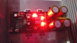
My negative reg side seems not working normal. Group of 5 leds light glow is very low, but none of them are dead. Measured voltage on V- is -20V while V+ is working good at +10.4V. I'm using 2x15V transformer.
I also try with 2x12V trans and measured V- is -16V and V+ is +10.4V
What parts should I check and replace if needed?
I also try with 2x12V trans and measured V- is -16V and V+ is +10.4V
What parts should I check and replace if needed?
Attachments
If you have -20V where it should read -10V then the regulator is not working.
That will make the follower/CCS buffer run very hot. Maybe even damage these 4 jFETs.
A downstream fault in the relay and it's drive circuit cannot cause the regulator to run High.
Have you checked the AC input voltage, the DC input voltage at the smoothing caps?
That will make the follower/CCS buffer run very hot. Maybe even damage these 4 jFETs.
A downstream fault in the relay and it's drive circuit cannot cause the regulator to run High.
Have you checked the AC input voltage, the DC input voltage at the smoothing caps?
DCB1 gain adon, OR Stand alone BOZ PCB !
Here we go!
On Salas suggestion, i decide to add some gain to DCB1 using good old Bride of Zen ...
Here is PCB layout, preliminary version ...
... is someone want to build, will provide gerber files!
•
Here we go!
On Salas suggestion, i decide to add some gain to DCB1 using good old Bride of Zen ...
Here is PCB layout, preliminary version ...
An externally hosted image should be here but it was not working when we last tested it.
An externally hosted image should be here but it was not working when we last tested it.
An externally hosted image should be here but it was not working when we last tested it.
An externally hosted image should be here but it was not working when we last tested it.
An externally hosted image should be here but it was not working when we last tested it.
... is someone want to build, will provide gerber files!
•
Its a minimalistic MOSFET way to add gain when in need. The DCB1 will buffer the BOZ output pot. Which can even be of higher value than the BOZ original 5K one now. As for printing the PASS logo and circulating a BOZ gerber I would ask Mr. Pass first if I was you.
Will do ... just emailed him ...
OK, approved by Papa, and redesigned a bit ...
Also, new PCBs, with separate PSU and single PreAmp channel ...
•
Also, new PCBs, with separate PSU and single PreAmp channel ...
An externally hosted image should be here but it was not working when we last tested it.
An externally hosted image should be here but it was not working when we last tested it.
An externally hosted image should be here but it was not working when we last tested it.
An externally hosted image should be here but it was not working when we last tested it.
An externally hosted image should be here but it was not working when we last tested it.
•
Hi,
Will you be organizing a group buy on this? I am interested.
Nope, i am not running group buy, gonna make some PCBs for my self ... Just some idea to add gain to DCB1 and similar preamps ...
How's this?
I can't find the dcb1 buffer build guide. It was a pdf of 2 pages, has anyone got it?
An externally hosted image should be here but it was not working when we last tested it.
An externally hosted image should be here but it was not working when we last tested it.
I can't find the dcb1 buffer build guide. It was a pdf of 2 pages, has anyone got it?
- Home
- Source & Line
- Analog Line Level
- Salas hotrodded blue DCB1 build