If you need a signal bandwidth exceeding 500kHz, then there may be an advantage in retaining the 33k resistor...............My question : is it good to add 33K resistor paralel with 100K attenuator to make 25K total impedance?
For normal audio the 33k is not needed.
The DCB1 with a 100k vol pot passes all the needed audio information.
The Power Amplifier will, or should, have an RF attenuator that rolls off the source signal well below 500kHz.
Last edited:
Salas/Andrew, can you elaborate the result in human language and easier to understand by end user like me? I'd like to try different value 10K 25K 50K 100K but also want to know the impact based on theory.
Edit:seems that Andrew has replied while I typed on my handphone")
Edit:seems that Andrew has replied while I typed on my handphone
Attachments
Last edited:
high output Sources like CDP (2Vac to 2.3Vac) and high gain Power Amplifiers (+27dB to +33dB) require a lot of attenuation for loud listening in a domestic environment and even more attenuation for normal and quiet listening.
Lower Gain Power Amplifiers would better suit domestic style reproduction of music and audio.
Until low gain Power amps become the norm, we are stuck with using attenuators @ -40dB to -20dB for most of our listening hours.
The output impedance of a 100k attenuator when set to -40dB is ~1k & when set to -20dB ~10k
Salas, my humble 2 cents allot of listening happens at 10% if the power amp has sufficient gain or efficient loudspeakers. Maybe 10% would be a better data point. Anything above that ratio is just going to get better
It gave better frequency when set to 1/4 (9 o'clock). Many here use an F5 and no more than 87-90dB SPL/W speakers though.
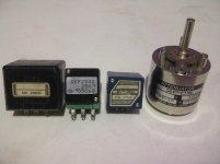
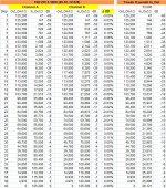
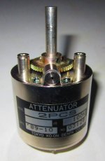
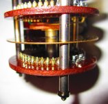
TKD 2PCS 100K measurement
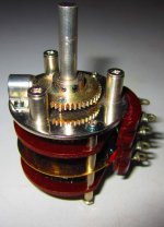
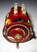
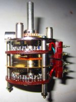
I just completed measuring this tkd by using sanwa pc500a dmm and the result on attached pict 1&2. Channel matching is very good, when I measure from In to Gnd, the result on dmm always shows 125.2 kOhm from step 1 to 40. I think that this tkd is series type based on measurement result and pict 3 explanation.
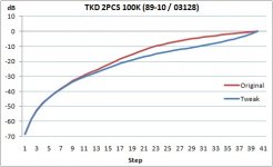
To keep Salas sugestion @25K and keep full attenuation capability, I'm planning to tweak it with R paralel 33K from Out to Gnd, where calculation seems good.
Other pictures are just reference for anyone if interested, since I can't find much info about this att on google. Another exploration is that on first 20 steps are using smd resistor,while next 20steps are using very small through-hole resistor.
I just completed measuring this tkd by using sanwa pc500a dmm and the result on attached pict 1&2. Channel matching is very good, when I measure from In to Gnd, the result on dmm always shows 125.2 kOhm from step 1 to 40. I think that this tkd is series type based on measurement result and pict 3 explanation.
To keep Salas sugestion @25K and keep full attenuation capability, I'm planning to tweak it with R paralel 33K from Out to Gnd, where calculation seems good.
Other pictures are just reference for anyone if interested, since I can't find much info about this att on google. Another exploration is that on first 20 steps are using smd resistor,while next 20steps are using very small through-hole resistor.
Attachments
Do you know what attenuation that represents?...................and I usually have my DCB1 volume knob at or slightly above 12:00 (or let's say between 10:00 and 2:00). .............
-6dB, -12dB, -18dB, -24dB ref maximum source output?
Hi,
I made a DCB1 in the past for SE application: JFETs have really tight Idss matching, resistors are Takman with 2% tolerance.
Since I'm about to build a BA-3B, I'm willing to convert the actual DCB1 chassis into balanced, putting in another board.
I therefore have some questions:
- should I check for matching the Takman resistor already used in my DCB1 build? Is matching necessary?
- what is the most simple but effective solution to have a volume control at inputs? I read about Figure 17 config_B. It basically adds two resistor in series with the + and - signal, and puts a variable resistor across the + and - signal. In this way I can use the same stereo potentiometer (is 25k still recommended for balanced application?).
Any help or suggestion is really appreciated!
Giulio
Balanced impedance connections ONLY give the interference rejection when the IMPEDANCES are matched. Very good rejection of interference requires very accurate matching of impedances.
Resistors to much better than 1%, preferably <0.02% (=+-0.01%)
Capacitors to much better than 10%, preferably <0.2%, since the main effect is just outside the passband, we can get away with a lesser standard of matching of the reactances.
Inductors if they exist would also need matching, but they are likely to be the inductance of the cable pair.
The physical layout may require to be changed to reduce the loop area of the inputs. Converting to XLR from twinned RCAs might be required.
I used to think that configuration B was OK, until I read D.Self........................
- what is the most simple but effective solution to have a volume control at inputs? I read about Figure 17 config_B. It basically adds two resistor in series with the + and - signal, and puts a variable resistor across the + and - signal. In this way I can use the same stereo potentiometer (is 25k still recommended for balanced application?).
................
Now configuration A (without the chassis connection) seems to be the way.
Read D.Self, he has a lot of papers on Balanced connections.
Worth reading Rane and Jensen (Whitlock) as well.
I found Balanced Line Technology , but I can't figure how configuration B is not OK.I used to think that configuration B was OK, until I read D.Self.
This would imply to use two variable resistors per channel, and they must be matched at every attenuation level... or?Now configuration A (without the chassis connection) seems to be the way.
Read D.Self, he has a lot of papers on Balanced connections.
Worth reading Rane and Jensen (Whitlock) as well.
Do you know what attenuation that represents?
-6dB, -12dB, -18dB, -24dB ref maximum source output?
I did when I built it... Now if I could just find that scrap of paper where I wrote down the measured resistance at each step. It was one of those log taper stepped attenuators from Ebay, I think 21 positions or so, smd 1% resistors. I think it was 25k. The 2 channels tracked very well.
I am very glad you asked. I just checked and it turns out I had the knob on the shaft such that fully cw was 6:00 and fully ccw was about 7:30. So 12:00 was 12 steps down from full volume, and was actually less than half rotation. I have shifted the knob on the shaft so now 12 steps down is about 10:30. I guess my gain structure was not what I thought it was!
Sad but true. I know my phono preamp has about 60dB of gain. I know that my DCB1 has 0dB of gain, and some attenuation. My power amps are a little more difficult, since they are integrated on a board with crossover and equalization, see Pluto electronics . The output stage has 21.6dB of gain, and the input stage has 8.6dB of gain, but I don't know what the other stages contribute in terms of gain and/or insertion loss. Of course I measured it all rather carefully when I built it and compared to Mr. Linkwitz's published specs, using his test CD, but that was more to measure relative gain at spot frequencies, rather than end-to-end gain of the circuit. Likewise, I measured my volume control when I got it before soldering it into the circuit, but not to look at specific attenuations but rather to see whether the 2 channels tracked well. Like most volume controls, the tracking was excellent in the area where attenuation was least, and poorest at the other end.
Now in my previous system, using an Arcam integrated amplifier and Tangent bookshelf speakers, I found that turning the volume control above 9:00 or 10:00 was getting uncomfortably loud; I certainly never had it to the half-way rotation point. This was also true using the preamp outs of that amplifier to drive the Plutos. I was pleased that with my DCB1 I can use the middle part of the rotation of the volume control for normal listening -- the reason that makes me happy is that I feel that this gives me better control of the volume (as opposed to a volume control that can only be used through 1/4 of it's rotation) and keeps the volume control in the "better" part of it's rotation where tracking is excellent.
Now in my previous system, using an Arcam integrated amplifier and Tangent bookshelf speakers, I found that turning the volume control above 9:00 or 10:00 was getting uncomfortably loud; I certainly never had it to the half-way rotation point. This was also true using the preamp outs of that amplifier to drive the Plutos. I was pleased that with my DCB1 I can use the middle part of the rotation of the volume control for normal listening -- the reason that makes me happy is that I feel that this gives me better control of the volume (as opposed to a volume control that can only be used through 1/4 of it's rotation) and keeps the volume control in the "better" part of it's rotation where tracking is excellent.
- Home
- Source & Line
- Analog Line Level
- Salas hotrodded blue DCB1 build