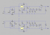
Good question. Looks like this. I believe it's something John Curl has used but I picked it up off EVUL's F5 headamp thread.
I believe it should work well but you would know better than I. It's what I already have, so it's nice to reuse parts.
This system will be primarily set up as a headphone system for at work but if I like the DCG3 I might do another one as a preamp in my main speaker system where I am currently using the Pass BA-3 front end in front of a dual pair mosfet F5. If I replace the BA-3 with the DCG3 it will be fed with a Jung regulator or your shunts. But we will see how the small chassis version I am making now sounds...
Attachments
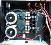
Here is today's progress. I got the second trafo in the mail yesterday so today I managed to stuff everything into a 3U galaxy chassis and get the PSU up and running. +/-17.6 vdc on both PSU's. All of the signal wiring is coax, and I decided to order a new 3position 4 pole selector switch instead of using a old six position 2 pole radio shack switch that I has laying around, that way I can keep the input grounds separate. I don't know if it will make much of a difference but it can't hurt. Everything else is ready to go, hope the switch comes quickly.
Paul
Paul
Attachments
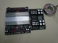
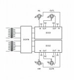
While waiting for another transformer and some heatsinks, I make plans for layout and wiring. Separate psu for each channel but each DCSTB module with 2,5" heatsinks will feed one DCG3 module biased @ 100mA. Theory says that the antiphase balanced signal is self compensating for reduced psu modulation. Plus the DCSTB will be loaded for lower output impedance! Gain will be set @6x - R6 = 2k5 - plus 6db for balanced mode(?) I' m very curious to listen to this!
Attachments
Hi Salas,
I was planning to use the case as a heat sink. I have made a smaller sink out of some aluminum stock, about 7 in long, 2 1/2 in wide, 1/4 inch thick. The mosfets are mounted directly to that, and the sink bolts directly to the case side. Much easier to take apart if needed without disturbing the mosfets.
Paul
I believe it's something John Curl has used but I picked it up off EVUL's F5 headamp thread.
I'm not sure how the rumor started about Mr. Curl designing or using this supply.
I asked him about it a while back and his reply was he had never seen the circuit before, though he liked it.
Then he asked if I was the one who designed it.
I just laid out a board for it and have 10 on the way.
Looking forward to trying it.
![IMG_20170109_092722[1].jpg](/community/data/attachments/528/528311-b57d0f24fe77d9e561f0f60d08bd1faf.jpg)
What are the two violet and one black wire doing? Connected to a common chassis bolt?Here is today's progress. I got the second trafo in the mail yesterday so today I managed to stuff everything into a 3U galaxy chassis and get the PSU up and running. +/-17.6 vdc on both PSU's. All of the signal wiring is coax, and I decided to order a new 3position 4 pole selector switch instead of using a old six position 2 pole radio shack switch that I has laying around, that way I can keep the input grounds separate. I don't know if it will make much of a difference but it can't hurt. Everything else is ready to go, hope the switch comes quickly.
Paul
The loop areas at the input sockets are very big.
The exposed core should be very much shorter.
The pig tail should be much shorter.
Aim to keep the short pigtail very close to the core for low loop area. It would be better to have two smaller pigtails, diametrically opposed and connected to the barrel beside the core/Hot

250mA with 10R source pin resistor for DN2540 is unlikely. 150mA with much high Vgs ones for that resistor value I have seen, but much more mA is suspicious for either wrong testing or fake components.
How you test? Where you tie the gate? It must be connected together with the free end of the 10R to battery (-) through a 330R gate stopper resistor very near to the gate not to oscillate
How you test? Where you tie the gate? It must be connected together with the free end of the 10R to battery (-) through a 330R gate stopper resistor very near to the gate not to oscillate
Yes I know Patrick, thanks, I just clarify for the readers. Most samples come around Hikari1's range in post #839. I have seen them giving from 98mA to 135mA on 10R with a matched pair from UK seller old batch exception at 150mA. Tea have been through literally hundreds for the GB to pair with bias resistors and never told me there are such odd ones like above 200mA on 10R. If its an old batch rarity that Marra got then alright he can put 25R and hit 100mA.
Marra,
try plotting your values onto the graph provided by Euvl.
Vgs = 2.5V, Id = 0.25A
Do this for each DUT.
See where they lie in comparison to the graph.
See how they compare to the maximum and minimum stated in the datasheet.
Then decide if your DUTs are genuine, or not.
try plotting your values onto the graph provided by Euvl.
Vgs = 2.5V, Id = 0.25A
Do this for each DUT.
See where they lie in comparison to the graph.
See how they compare to the maximum and minimum stated in the datasheet.
Then decide if your DUTs are genuine, or not.
Hi MagicBus,
I'm really curious how your pre-amp works out, because I'll go the same route. But I have to wait at least 2 more months before I can start doing this!
Have fun and please report back!
Matthias
I'm really curious how your pre-amp works out, because I'll go the same route. But I have to wait at least 2 more months before I can start doing this!
Have fun and please report back!
Matthias
While waiting for another transformer and some heatsinks, I make plans for layout and wiring. Separate psu for each channel but each DCSTB module with 2,5" heatsinks will feed one DCG3 module biased @ 100mA. Theory says that the antiphase balanced signal is self compensating for reduced psu modulation. Plus the DCSTB will be loaded for lower output impedance! Gain will be set @6x - R6 = 2k5 - plus 6db for balanced mode(?) I' m very curious to listen to this!

- Home
- Source & Line
- Analog Line Level
- Salas DCG3 preamp (line & headphone)