Yes,same.same result when only one channel connected?
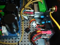
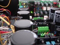
The amplifier pcb is isolated mounted on the heat spreader? The first prototype pcbs have the screw fields erroneously unisolated ...
115mV for the CONNECTED channel ,7mV when laptop mute.
70uv for the DISCONNECTED channel.
I have isolate the mounting holes on the bottom using a dremel.
Last edited:
Yes, i must put my ear in contact with the tweeter to be able to hear a very low level noise.You have said you can hear nearly no noise with the ear on the speaker. maybe you measure some dac artefacts. laptop soundcards often have bad output filters and your amp has a very high power bandwidth.
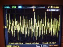
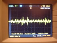
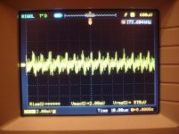
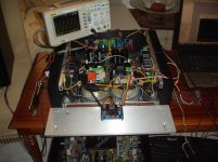
use your scope to check the output signal frequency and amplitude.
I tried to pull the jack and short this using an aluminium paper, the measurement is 0 mV.
The cable is like this but 1.5m
Attachments
Last edited:
Which way?A scope will bring light into darkness...")
Do you mean a new test using a generator and a scope seeing square waves?
I'm afraid that i can't understand what is this signal.No - just looking what kind of signal generates such noise or offset...
BR, Toni
This was measured at the output of the amplifier.
Attachments
Last edited:
I can't see problem except when an earthed switch mode power supply used for the laptop.DAC artefacts maybe mixed with switching power supply artefacts.
gracefully to be ignored.
Have fun with your soon finshed amplifier!
Congrats!
BR, Toni
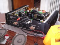
I will post pictures from the semi finished amplifier soon.
Thanks Toni!
Last edited:
Dear Thimios,
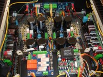
looks pretty good!
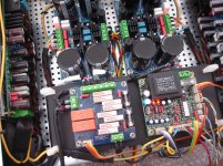
I would do one change: the small signal lines (ribbon cables) route above in the middle of the amplifier. The sharp edges from the steel bottom may destroy the cables.
The signal cables carry only constant DC and speaker output signals decoupled by 4.7k (for DC detection).
BR, Toni
looks pretty good!
I would do one change: the small signal lines (ribbon cables) route above in the middle of the amplifier. The sharp edges from the steel bottom may destroy the cables.
The signal cables carry only constant DC and speaker output signals decoupled by 4.7k (for DC detection).
BR, Toni
Dear Toni,don't worry!Dear Thimios,
looks pretty good!
I would do one change: the small signal lines (ribbon cables) route above in the middle of the amplifier. The sharp edges from the steel bottom may destroy the cables.
The signal cables carry only constant DC and speaker output signals decoupled by 4.7k (for DC detection).
BR, Toni
I will take care in the finally assembled amplifier.
I will enclose this ribbon cable (at these <<dangerous>> points) in a thermal shrinking tube.
Thanks a million!
Thimios
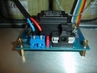
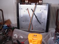
Yes the big hole is 12mm and must be 16mm,16mm don't fit in my drill Machine.
I see you have done some machining for the big power button and standby led too!
BR, Toni
I will need friend's help again!
Last edited:
- Status
- This old topic is closed. If you want to reopen this topic, contact a moderator using the "Report Post" button.
- Home
- Amplifiers
- Solid State
- SA2015 V-MOSFET Builders