Ok so this testcard I made doesn't seem to be right, I read the manual and checked all the pins and it did make sense and I honestly thought it would work.
However after heating up a tube for a short time some smoke came from the tester, I quickly removed the tube and re-did the card and tried again with same result.
Maybe someone can tell me what's the flaw in this test card? Hope I didn't really destroy anything in the tester... seems to still work though.
Attachments
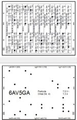
There was for some reason no connection made for grid No. 1 (No plug)! Should have been plug 44/I. Which version of my software were you using, I want to try to reproduce that, the latest snapshot sets the connection for G1 properly.
Therefore, when heated up the tube may have drawn way to much plate current (because of Ug1=0V) and overloaded the supplies by that. Since that are tube regulators, the damage to them should be limited, but maybe some of the (unfortunately) custom shunts are damaged. I recommend to check that.
I'm sorry for that unfortunate outcome, but I thank you a lot for taking the risk of alphatesting.
Yes I don't know what happened, I was sure I had it set right but having a 2nd look it now works just fine!
I think I was just so busy checking that everything that was there was configured right that I forgot to check for what was missing
Would there be any reason why my tester seems to indicate lower than it should for S reading on all tubes? (it has always done that, it didn't just happen now after this incident.)
For example it seems to give S reading of about 3-4 when it should be showing 5.5'ish and more. Seems to be more exaggerated on tubes with higher ma/v, for example new 1625 reads 4'ish and should be 6'ish. So it's a good 25% low.
Cerker, I don't think your software did anything wrong, I might have just not clicked it properly when I was using the scroll menu, sometimes scroll menus are like that. Alternatively, could it reset itself if you change the other items later? It was the first one, the one with the save picture error.
I have to say I am very happy that you made this software it's fantastic that someone would do this.
I think I was just so busy checking that everything that was there was configured right that I forgot to check for what was missing
Would there be any reason why my tester seems to indicate lower than it should for S reading on all tubes? (it has always done that, it didn't just happen now after this incident.)
For example it seems to give S reading of about 3-4 when it should be showing 5.5'ish and more. Seems to be more exaggerated on tubes with higher ma/v, for example new 1625 reads 4'ish and should be 6'ish. So it's a good 25% low.
Cerker, I don't think your software did anything wrong, I might have just not clicked it properly when I was using the scroll menu, sometimes scroll menus are like that. Alternatively, could it reset itself if you change the other items later? It was the first one, the one with the save picture error.
I have to say I am very happy that you made this software
it's fantastic that someone would do this.
Last edited:
Would there be any reason why my tester seems to indicate lower than it should for S reading on all tubes? (it has always done that, it didn't just happen now after this incident.)
For example it seems to give S reading of about 3-4 when it should be showing 5.5'ish and more. Seems to be more exaggerated on tubes with higher ma/v, for example new 1625 reads 4'ish and should be 6'ish. So it's a good 25% low.
Where do you take your reference values from. Are they from the datasheet for exactly this operating point?
I ask because "simpler" transconductance testers tend to show higher than real values, because they don't filter out hum and harmonics, as the L3-3 does. Actually, it measures the transconductance EXACTLY according to its mathematical definition, especially because it eliminates the ac plate voltage in the power supply (the plate voltage sense divider is connected after the plate shunt resistor).
Since the calibration routine puts a tap from the range divider directly to the selective amplifier, errors both in the oscillator and amplifier (and measuring instrument) are effectively compensated. Critical is the range divider and the plate shunt resistor, because the calibration relies on them as precision reference resistors. So one of those should be bad, I think.
Cerker, I don't think your software did anything wrong, I might have just not clicked it properly when I was using the scroll menu, sometimes scroll menus are like that. Alternatively, could it reset itself if you change the other items later? It was the first one, the one with the save picture error.
That can happen if you change the tube socket after doing some settings. When a special connection is not available at this socket, it will get reset. Nothing should happen if you "fill out the form" from top to bottom.
But your incident showed to me that I should think of implementing some sort of sanity checking, e.G. if all grids are connected and warn the user if thats not the case. I will keep that in mind for later versions.
I have to say I am very happy that you made this software
Thanks, I hope it will help many people.
I just did an attempt to fix that problem, now there are 2 additional pin functions available:
Heater(+) & Cathode
Heater(-) & Cathode
NEVER assign both of them, that will short circuit the transformer!
The next alpha release will have some sanity checking, which forbids to do that. But at first you can check with a few cards if it works basically correct.
Heater(+) & Cathode
Heater(-) & Cathode
NEVER assign both of them, that will short circuit the transformer!
The next alpha release will have some sanity checking, which forbids to do that. But at first you can check with a few cards if it works basically correct.
I didn't have much spare time on my hands the last months and since I had much software coding to do at work .. I wanted to relax a bit from doing that at home.
However, I already started a new version from scratch because the old one was very nested between the various functions and trying to add the last few features ended in a deadlock sometimes. And, good news .. I'm doing a long vacation the next weeks where I'm going to finish all those halfdone projects.
However, I already started a new version from scratch because the old one was very nested between the various functions and trying to add the last few features ended in a deadlock sometimes. And, good news .. I'm doing a long vacation the next weeks where I'm going to finish all those halfdone projects.
Ok thanks for answering, and looking forward to being part of your test team. I've just got my hands on another L3-3(my second one) and it does not have any cards so a PC program in English would be perfect. But no rush I'm still in the process of fixing it up, waiting for a 6Z3P and a 6P1P tube and also maybe it needs new push buttons. The main problem is that I get no heater voltage reading on the meter, however heater voltage readings taken with another digital meter indicate that the heater voltage is present and correctly adjustable.
thanks
thanks
I have some and can give one for free. Anyway you still have to adjust your L3 when you replace the meter though.
PM sent
My L3-3 no longer measures transconductance properly. When doing the internal calibration (tuning freq and voltage with the pots behind the left door) I can not get the S calibration signal to the 120 calibration mark on the L3-3 meter. Even with the external calibration pot on the front on max, I can't get past 80....
I guess the following strange behaviour is related to it. Doing the internal calibration, one should normally find the strongest signal around 1400Hz, when the amplitude is set to 0.45 V. In my L3-3, the lower frequency the tone generator can make is around 1260 (pot turned fully left). When I increase the frequency with the corresponding pot, 1373 is the maximum frequency I can reach. Turning the pot any further immediately results in a total collaps of the generator signal (0 hz readout). So: my generator seems unable the get high enough to reach the frequency at which the signal is strong and midway the bandpass filter.
When I did measurements about a year ago, I could still get to about 1400Hz (after that , the signal collapsed too, but that was no problem as the S readout on the L3-3 meter was than more than strong enough to calibrate to the 120 level). My hypothesis is therefore that the frequency band that can be generated has shifted down, outside of the desired range near 1400.
Any hints what the cause of the problem is? Are there perhaps parts whose values have run out of spec? I'd appreciate hearing your thoughts on this!
I had similar problems, I would first check R138 (normally around 18k) and replace both internal pots, or atleast dismantle the 2 pots (R155 and R157) and clean them. If you do replace them be sure to check what resistances are actually written on them, which can differ from what's found on the schematic.
Thanks! Given the odd total collaps of the signal while turning the pot up your suggestion really makes sense. Because I bought the L3-3 NOS (sure about it, was in crate and still wrapped in brown paper that had gone very brittle over time - that fell apart during unpacking), I kind of rules out the pots as the problem in my head. But the quality of them may simply be poor and may have suffered over time too. I'll give it a try asap.
I would strongly suggest you change out the pots and also C41if you haven't already done that. Even if the pots give good dc resistance that doesn't mean that the whole resistive track is clean or fully functioning, try dismantling them first and clean the insides... the best thing would be to get new pots and start from there.
- Home
- Design & Build
- Equipment & Tools
- Russian L3-3 tube tester