Great job! Enjoy the windows experience as much as i have already!Yes, you are right! I just compared my ssd contents with your image contents, and these files have changed indeed. The serial number also matches the one on the case.
I have double checked with the Service Manual, which I have just found on your Google Drive, and there it also says that if calibration data is found in both I2C EEPROM and on the harddisk, the first takes precedence and the data on the harddisk is overwritten. That makes sense, but I feared the first.
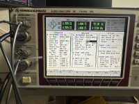
And just so you know; My UPL is booting your Windows 98 image now, and the UPL application runs. I didn't do any measurements with it, but it pases its selftest, and no errors are reported. It was a long journey, though. I could describe it here, but it involves a lot of Linux terminal commands, probably not to everybody's taste here...
Here's how I added external USB connectors:


One is intended for a USB Ethernet dongle. Sub-ideal for performance, but more than good enough for getting files on and off the instrument.
The other will be connected to a hub, for a mouse and a flash drive.
I have considered to replace the FlexiDrive with a floppy hybrid drive, that contains both a floppy drive, various card readers and a front panel USB-A connector. I may still do that, if I can find a beige one. Together with this 'splitter', which are actually 2 internal 2-port hubs, everything could be connected simultaneously.
I got the board measurements from (Bart I think) some time back, and am currently working on a cloned PCB for the digital outputs. The board is deceptively complicated as there's not much space to fit it in the instrument, and there are actually a lot of components on itOk then in such case and if you are familiar with PCB design I think that this front panel is not so complex to clone.
You need to ensure that you can source all the parts on it or find equivalent as they are a bit old but it should be doable.
The front panel is relatively simple.
")
I've managed to source the completely obsolete parts from various obscure corners of the Internet, let's hope I can get it going!
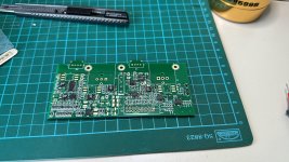
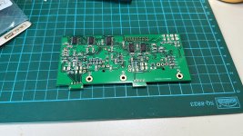
I've gotten the preliminary (unrouted) board layout from a local guy who does PCB design, it's currently off to JLCPCB for production so that I can mount the front panel components to check fit.
As you can see the board is really dense due to the ability to adjust output levels etc. so it is non-trivial to build one without a PCB.
I have the nagging suspicion that this is going to be quite an expensive project, but it should be worth it as I'll then have a practically fully loaded UPL with the (seems to be extremely rare) B29 96kHz option.
Looks really cool! Let me know if you need anything from my side.I've gotten the preliminary (unrouted) board layout from a local guy who does PCB design, it's currently off to JLCPCB for production so that I can mount the front panel components to check fit.
As you can see the board is really dense due to the ability to adjust output levels etc. so it is non-trivial to build one without a PCB.
I have the nagging suspicion that this is going to be quite an expensive project, but it should be worth it as I'll then have a practically fully loaded UPL with the (seems to be extremely rare) B29 96kHz option.
View attachment 1123823
Bart
Hi Bart! If it’s not too much trouble it would be great if I had the detailed measurements of the metal bracket that the digital I/O mounts to, so I could make a 3D printed version. I scaled the PCB outline from the service manual based on the photos of the board you previously provided, let’s hope it fits!Looks really cool! Let me know if you need anything from my side.
Bart
Will take some measurements tomorrow and of the critical PCB outlines and XLR plugs.Hi Bart! If it’s not too much trouble it would be great if I had the detailed measurements of the metal bracket that the digital I/O mounts to, so I could make a 3D printed version. I scaled the PCB outline from the service manual based on the photos of the board you previously provided, let’s hope it fits!
An update on my Windows 98 upgrade. During the past week I’ve spent way more time than I will probably every do on actually using this instrument on fixing a problem, that really isn’t a problem. But hey, you’re either committed, or not, right?
The ’problem’ i ran into was Windows complaining about .dll and .drv files being replaced by older versions by the ‘program i just ran’. And that program I just ran was the Windows (un)installer to remove the network card my instrument doesn’t have, FlukeView and Kprint. I could - and perhaps should - have chose not to bother, but what intrigued me, was that the files Windows mentioned, weren’t actually replaced, or even touched. Apparently, it expected a different version from it’s database, but didn’t bother to check, until I ran the installer. After many, many, many trial-n-error reinstalls of my image en unstalling iterms in different ways, I found a solution: The System File Checker can check all files and replace them if necessary (Start -> run -> sfc). When checking, nothing wrong was found, but after having it replace the first file reported from the Win98 install CD, it stopped complaining. Later, it started recomplaining about 2 other files, and this was fixed the same way.
To get USB mass storage devices working, I had to install a 3rd party USB stack. For Ethernet, I used a USB-FastEthernet dongle, and that works too. Unfortunately, SBM v1.0 authentication as used in Windows 98, had very poor security, and is hence disabled on all other platforms, so I still cannot share files with the instrument.
For my printer, I installed the Adobe PostScript driver. After pointing it to my modern printers .ppd file, it is now fully supported; Duplexer, stapler and puncher and all. That’s why we buy PostScript printers, folks; They are supported forever!
Oh, I didn’t do any actual measurements yet, but the UPL application launches just fine, so I don’t expect any problems there.
Update: using etherdfs and a pktdrv for a intel pci 10/100m card I was able to permanently mount a directory from a linuxserver running
On linux:
./ethersrv-linux -f eth0 /home/myself/instruments/upl/screenshots/
On UPL running freedos this bat is running as a TSR:
This adds a G:\ Drive which can be used to store the hardcopy data.
Afterwards the upl software can be started and configured using menu button "FILE": change the working directory from c:\upl\user to e.g. G:\
A screenshot goes then directly via network to your linux box.
Of course this solution works only in a broadcast domain (local lan) but is very fast - up to 100mbit.
The memory footprint of the etherdfs TSR is 8k
even
No need for a windows ...
Use "xcopy" command to transfer a large amount of data via e.g. drive G:\
BR. Toni
On linux:
./ethersrv-linux -f eth0 /home/myself/instruments/upl/screenshots/
On UPL running freedos this bat is running as a TSR:
rem loading packet driver only
c:\NETWORK\DRIVER\E100BPKT.COM -p 0x60 UTP FAST FULL
rem loading etherdfs
c:\etherdfs\etherdfs.exe :: C-G /p=60
This adds a G:\ Drive which can be used to store the hardcopy data.
Afterwards the upl software can be started and configured using menu button "FILE": change the working directory from c:\upl\user to e.g. G:\
A screenshot goes then directly via network to your linux box.
Of course this solution works only in a broadcast domain (local lan) but is very fast - up to 100mbit.
The memory footprint of the etherdfs TSR is 8k
even
No need for a windows ...
Use "xcopy" command to transfer a large amount of data via e.g. drive G:\
BR. Toni
Hi Toni,
It looks nice but I prefer FTP or SMB(windows file sharing) because they have more universal availability.
I am currently using SMB on R&S UPD as a server side (It works as TSRs with R&S app), but SMBv1 support will be completely dropped on win11 soon.
I will try mTCP FTP server on win 3.1, multitasking with R&S app.
No need for ftp or smb
etherdfs works very fast.and using the B10 option you can completely remote control your UPL. An example:
Asume we have started
then I can do something like:
My etherdfs server is running under linux using the local subdir "/home/toni/pcb/upl/workdir" which is mapped at the UPL as drive "G:\"
=> above commands makes me a screenshot in the desired share and the resulting file can be used directly under
The UPL powerful SCPI commands (listed in manual 3.9 Common Commands, p. 528) allow you even to copy files from drive G to local drive and vice versa. Execute "*.bas" files and so on. No need for a windows at the upl.
Of course this works currently under linux only, but may be compiled for windows linux subsystem too.
The memory footprint of the pktdrv and etherdfs client is very low.
BR, Toni
etherdfs works very fast.and using the B10 option you can completely remote control your UPL. An example:
Asume we have started
- etherdfs "server" and "client"
- UPL Com2 connected to the linux box using a null modem cable to a com port e.g. ttyS4
then I can do something like:
toni@mypc:~/upl> ./rs_com_terminal.pl
1679840512.77189 RX:524f484445202620 5343485741525a2c 2055504c2c20332e |ROHDE & SCHWARZ, UPL, 3. |
1679840512.78198 RX:30362c20302e3333 0a |06, 0.33 ? |
*IDN?
1679840524.67159 TX:2a49444e3f0a |*IDN?? |
1679840524.68171 RX:524f484445202620 5343485741525a2c 2055504c2c20332e 30362c20302e3333 |ROHDE & SCHWARZ, UPL, 3. 06, 0.33|
1679840524.68172 RX:0a |? |
HCOP:DEST FIPS, 'SCREEN02.PS'
1679840549.30578 TX:48434f503a444553 5420464950532c20 2753435245454e30 322e5053270a |HCOP:DES T FIPS, 'SCREEN0 2.PS'?|
MMEM:CDIR "G:\"
1679840567.81523 TX:4d4d454d3a434449 522022473a5c220a |MMEM:CDI R "G:\"? |
HCOP
1679840569.75660 TX:48434f500a
My etherdfs server is running under linux using the local subdir "/home/toni/pcb/upl/workdir" which is mapped at the UPL as drive "G:\"
=> above commands makes me a screenshot in the desired share and the resulting file can be used directly under
mypc:/home/toni/pcb/upl/workdir # dir /home/toni/pcb/upl/workdir/screen02.ps
-rw-r--r-- 1 root root 7075 26. Mär 16:22 /home/toni/pcb/upl/workdir/screen02.ps
The UPL powerful SCPI commands (listed in manual 3.9 Common Commands, p. 528) allow you even to copy files from drive G to local drive and vice versa. Execute "*.bas" files and so on. No need for a windows at the upl.
Of course this works currently under linux only, but may be compiled for windows linux subsystem too.
The memory footprint of the pktdrv and etherdfs client is very low.
BR, Toni
Example UPL-B10
1679842066.08072 TX:0a |? |
*RST
1679842075.43752 TX:2a5253540a |*RST? |
*IDN?
1679842086.23143 TX:2a49444e3f0a |*IDN?? |
1679842086.24155 RX:524f484445202620 5343485741525a2c 2055504c2c20332e 30362c20302e3333 |ROHDE & SCHWARZ, UPL, 3. 06, 0.33|
1679842086.24157 RX:0a |? |
INP:TYPE GEN2
1679842094.78318 TX:494e503a54595045 2047454e320a |INP:TYPE GEN2? |
INIT:CONT OFF;*WAI
1679842099.70266 TX:494e49543a434f4e 54204f46463b2a57 41490a |INIT:CON T OFF;*W AI? |
SENS:DATA?
1679842104.36104 TX:53454e533a444154 413f0a |SENS:DAT A?? |
1679842104.37116 RX:302e353031393936 3537363738362056 0a |0.501996 576786 V ? |
HCOP:DEST FIPS, 'SCREEN03.ps'
1679842186.07616 TX:48434f503a444553 5420464950532c20 2753435245454e30 332e7073270a |HCOP:DES T FIPS, 'SCREEN0 3.ps'?|
MMEM:CDIR "G:\"
1679842194.34776 TX:4d4d454d3a434449 522022473a5c220a |MMEM:CDI R "G:\"? |
HCOP
1679842199.56033 TX:48434f500a |HCOP? |
Attachments
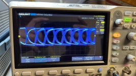
I have an UPL on my desk that is failing it's selftest quite dramatically. I'm hoping anyone here could help point in the right direction.
I'm suspecting a gain amplifier chip or something that is common for both channels.
See the failed selftest image as well as a passed and failed test result.

Any help is appreciated!,
Thanks,
Cheers,
Bart
I'm suspecting a gain amplifier chip or something that is common for both channels.
See the failed selftest image as well as a passed and failed test result.
Any help is appreciated!,
Thanks,
Cheers,
Bart
Attachments
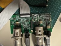
Well, after much pain and some money, I now have a front digital I/O for my UPL!
I had a local guy “clone” the layout of the board as best as he could, based on photos of the original board and the original schematics.
That many components took me the better part of 2 days to solder, not to mention having to trawl through sellers of questionable merit to locate all the obsolete parts.
Seems to work fine, apart from some teething problems caused by oxidation on the pins of the (really old stock) CLC430s.
Attachments
Hi @Bjirre ,
Would you happen to have any PCB layout files for the ISA slot adaptor?
I'm thinking of wiring in one of those ISA->USB adaptor cards (search for USB ISA on AliExpress), and don't wish to solder to the original.
Direct USB drive access would make life so much easier
edit: found them! https://github.com/bvksound/UPL_AudioAnalyzer
Last edited:
Thanks for the suggestion, but the issue is happening simultaneously on both channels on the board. Each Channel has their own relay and no relay is shared for both channels. Having a double relay failure would seem odd.Maybe a relay failure on the analog board near output stage. The relays control output gain and they are known to fail. I have had such a problem.
Open for any other suggestions though!
Thanks!
You have a built in low distortion generator: if all output levels at different frequencies are correct, then the output stage gain and attenuators are ok. Check the DAC outputs sheet 25+ section B1-B5 (service manual volume2 page 122-123).
Reading the results it seems to be a frequency related gain error in N79 and N80 opamp circuit?!?
Check the DACSIG amplitude at different frequencies be4 and after relay K238
Reading the results it seems to be a frequency related gain error in N79 and N80 opamp circuit?!?
Check the DACSIG amplitude at different frequencies be4 and after relay K238
- Home
- Design & Build
- Equipment & Tools
- Rohde Schwarz R&S UPL Audio Analyzer Renovation