Assembling FC-100
Few questions abut assembling FC-100 into the case.
As long as i have 4A fuses onboard do i still need a fuse for the primary of the transformers?
Do you think a multifilar cable of 1.5mm diameter to connect secondaries of transformers to the pcb's will do the job well?
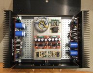
I've attached also a picture with my plan of positioning the components. The two power toroids are in the middle under the shunts pcb into a stainless steel case (Thanks to Rudi's idea) and also saved some space.
Few questions abut assembling FC-100 into the case.
As long as i have 4A fuses onboard do i still need a fuse for the primary of the transformers?
Do you think a multifilar cable of 1.5mm diameter to connect secondaries of transformers to the pcb's will do the job well?
I've attached also a picture with my plan of positioning the components. The two power toroids are in the middle under the shunts pcb into a stainless steel case (Thanks to Rudi's idea) and also saved some space.
Attachments
Allways...do i still need a fuse for the primary of the transformers?
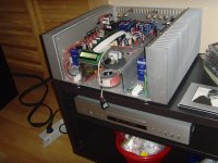
Adrian, your build looks good in my eyes, but: please do not waste space! Maybe you will need some space for additional PCBs in the future!
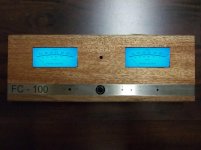
This is how I did it (see attached image).
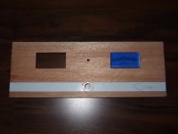
A good DIY-friend of mine is offering me one of two solutions for the front panel. The type of wood is called "Meranti".
I can choose between the "McIntosh Look" and the "LCD Look", but I still cannot decide.
Best regards - Rudi_Ratlos
This is how I did it (see attached image).
A good DIY-friend of mine is offering me one of two solutions for the front panel. The type of wood is called "Meranti".
I can choose between the "McIntosh Look" and the "LCD Look", but I still cannot decide.
Best regards - Rudi_Ratlos
Attachments
Yesterday evening i've put all the covers to my amplifier and had a long listening. The sound is really nice, the bass control is amazing but i think i have some problems with temperature compensation.
Last bias adjustment was without top cover and westerday with top cover mounted my bias went from 36mV to 45mV also overall case temepratuse went pretty high.
I'm running with one diode shorted and another one bypassed by BAT42.
My heatsinks are rated 0,31 C°/W (Mihai recommended 0.37C°/W) (Pessante disipante 4U 300mm depth)
What advice do you have for me ?
Also i believe my case is not ventilating very well and i was thinking if would be a good idea to install some small fans (i hate this idea of installing fans).
My BAt42 diodes are blue ones wich looks like plastic body, would be better to install the ones with glass body and orange colour ?
Last edited:
It seems that one of the TT-diodes isn't soldered (glued) correctly to the metal plate of the transistor.
To check for this, on have to heat-up the metal plate and measure the voltage drop over the diode and the junctions of the transistor (the diode and both junctions of the transistor forward biased at constant current). The diode voltage drop vs the voltage drop of each of the junctions must be as close as possible to a straight line.
In Adrians amp, I suppose one of the diodes is "popping up" like a bimetall.
Last edited:
Franzm assumption seems to be right as moving de diode jumper to another diode make bias a bit smooth but still rising slowly with temperature.
Discovered that on one channel i have shotky on a PNP transsitor and on the other one is on the NPN.
I will fix this issue and let you know about how things are changing.
Also i believe the heatsinks from frontend power supplies are a bit too hot, still i can keep my finger on them for few seconds.
Discovered that on one channel i have shotky on a PNP transsitor and on the other one is on the NPN.
I will fix this issue and let you know about how things are changing.
Also i believe the heatsinks from frontend power supplies are a bit too hot, still i can keep my finger on them for few seconds.
Today during my efforts to have a stable thermal compensation i've observed something interesting and i dont't know if it's normal or not: the voltage measured over Re (0.1R emitter resistors) is not equal between NPN and PNP power transistors.
Rudi designed the pcb to adjust bias measuring voltage over two Re from oposite rails and you need to get around 36mV but this 36mV are not equally distributed over the two resistors.
This behaviour is the same over the two channels.
Thanks !
Adrian
PS. now my amplifier looks very stable thermally but the case is not completely closed and is having a lot of space to "breathe"
Last edited:
You will find that all six Vre are different.
This comes about due to the six different Vbe and the six different Re.
Good matching of all the paralleled components is the only method of reducing these differences.
When no current flows to the Load and no current flows to the NFB and no current flows to the Zobel then the TOTAL upper current MUST be IDENTICAL to the TOTAL lower current, ie. Vre1+Vre2+Vre3=Vre4+Vre5+Vre6, when Re1=Re2=Re3 and Re4=Re5=Re6
It is to get the zero Load and Zobel and NFB currents, that we impose the testing conditions of open output and shorted input.
I think i've tamed the beast but i still have some issues.
First, i've installed the transistors with higher diodes on the upper part of the heatsink and installed BAt46 diodes also on the upper transistors. This gave me a smoother bias adjustment but what worries me and i dont know if everyone is having the same behaviour: voltage over two resistors the expected 36mV value rise with case temperature.
I have deviations of 3-5 mV from center point. When i adjust bias after 30min power up i have 31-32mV when cold and goes 40-41mV when i listen louder some time.
Is that normal or i still have problems ?
Last edited:
I have deviations of 3-5 mV from center point. When i adjust bias after 30min power up i have 31-32mV when cold and goes 40-41mV when i listen louder some time.
Is that normal or i still have problems ?
Hi Adrian,
It is normal to have some deviation between different Res but isn't normal to have positive deviation of bias with temperature. In fact, It should be otherwise. The output stage must be a little bit overcompensated.
Did you received my response at your last private message?
BR,
Mihai
Guys, those of you having bias related problems with this design either have fake NJL zero series transistors or non zero NJL transistors.
The correct behavior of this amplifier is a little bit overcompensated and the bias tracking with temperature is extremely fast.
The output stage starts at more than double bias current but will settle to 36mV over two REs in less than 30 seconds. After that, this bias level is maintained regardless of temperature or program level and the deviation must be under 2mV and settle back to 36mV in less than 2-3 seconds after any perturbations induced by loud listening were removed.
Last edited:
After all these efforts with thermal compensation i concluded my NJL transistors are from a wrong batch.
Because Onsemi was unable to fulfill my samples order i've bought some transistors from a very nice guy from this forum but they where sourced some time a go when i think some other people had my problems.
My sample order will be fulfilled in september if i remember well and i hope those ones will have the right diodes inside.
I think will be a nightmare to desolder and solder all those NJL from the pcb and not to destroy the pcb traces.
I think will be a nightmare to desolder and solder all those NJL from the pcb and not to destroy the pcb traces.
Not if you cut all the pins first, and remove them one at a time.
... not if you cut the pins first, cut the pins of the "new" NJLs as well and solder them to what has been left of the pins of the "old" NJLs.
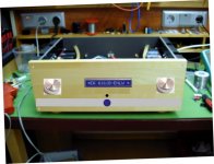
I am very unhappy to see your troubles, Adrian.
In the meantime I go on and do some "wood-work" on the front-panel of my FC-100 - case.
Best regards - Rudi
I am very unhappy to see your troubles, Adrian.
In the meantime I go on and do some "wood-work" on the front-panel of my FC-100 - case.
Best regards - Rudi
Attachments
- Status
- This old topic is closed. If you want to reopen this topic, contact a moderator using the "Report Post" button.
- Home
- Amplifiers
- Solid State
- Roender's FC-100 prototype and builder's thread